
In a substation, two transformers may appear similar from the outside but may operate differently when put under load. The reason for this difference is not because of the difference in the manufacturing of the transformers but due to the difference in thermal and electrical ratings as mentioned on the nameplates and literature. Understanding the specifications makes a difference between a knowledgeable specifier and an uneducated one who may need to change the transformer even three years before its useful life.
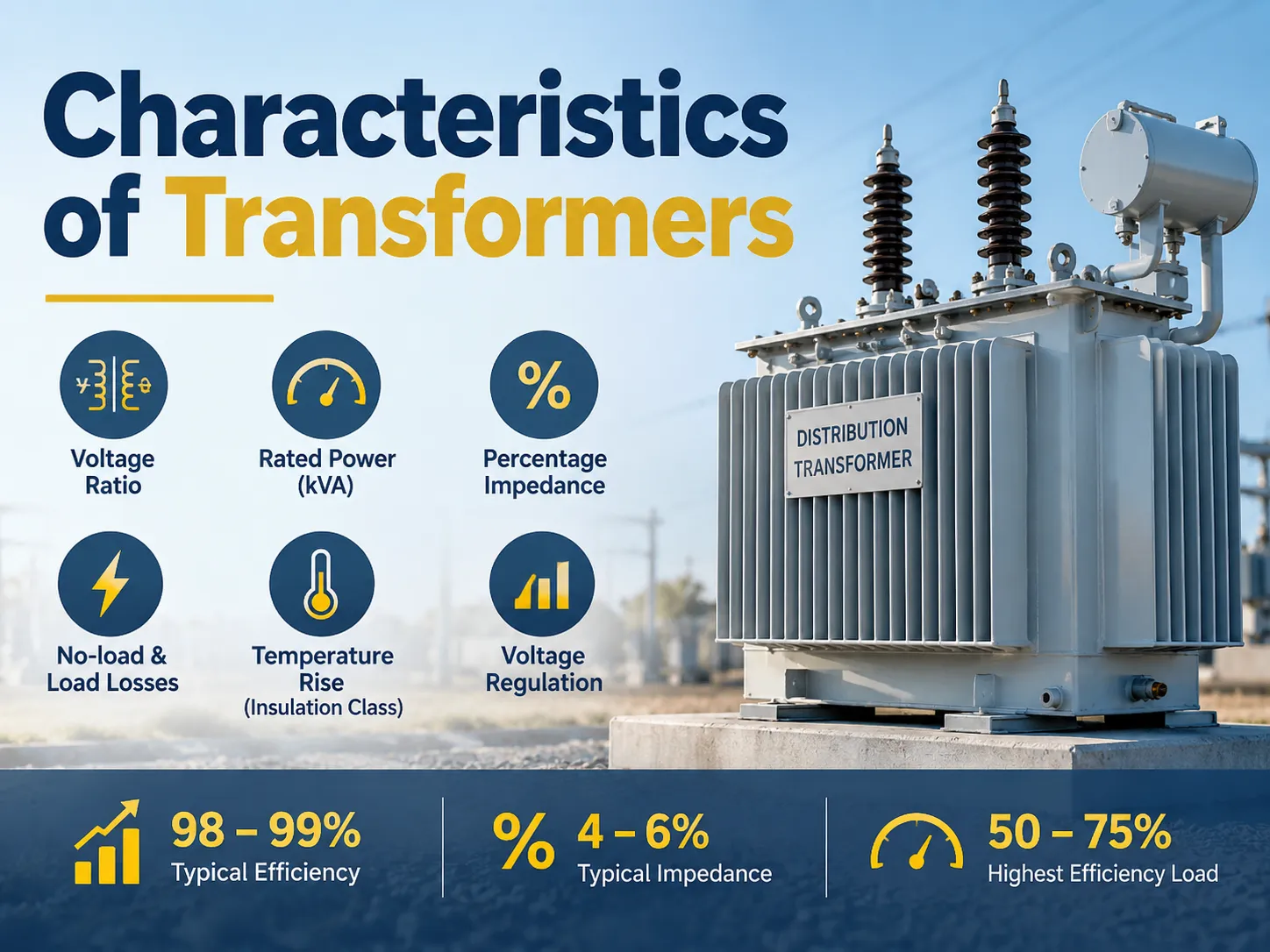
There are some important characteristics of transformers that one should know while assessing their performance such as the voltage ratio, kVA rating, percentage impedance, losses on full and no-load, rise in temperature according to the insulation class involved, and the voltage regulation. The efficiency of a distribution transformer is about 98 percent to 99 percent in operation, with the impedance in the range of 4 percent to 6 percent, with the peak efficiency obtained when the current reaching 50 percent to 75 percent of the rated load current level is flowing through it.
The Working Principle in One Paragraph
Transformers are electrical devices used to transmit energy through a magnetic field from one circuit to another. By varying the alternating current in the primary or first coil, a corresponding voltage is induced in the secondary or second coil through the magnetic field produced by the primary coil. Since the same magnetic vein passes through both coils, the voltages induced in each coil change in proportion to the number of turns in each coil. In fact, by varying the number of turns in either of the coils, we can also vary the voltage induced in either of the coils. In the process, there are no mechanical parts involved, and very large transformers have efficiencies over 99 percent.
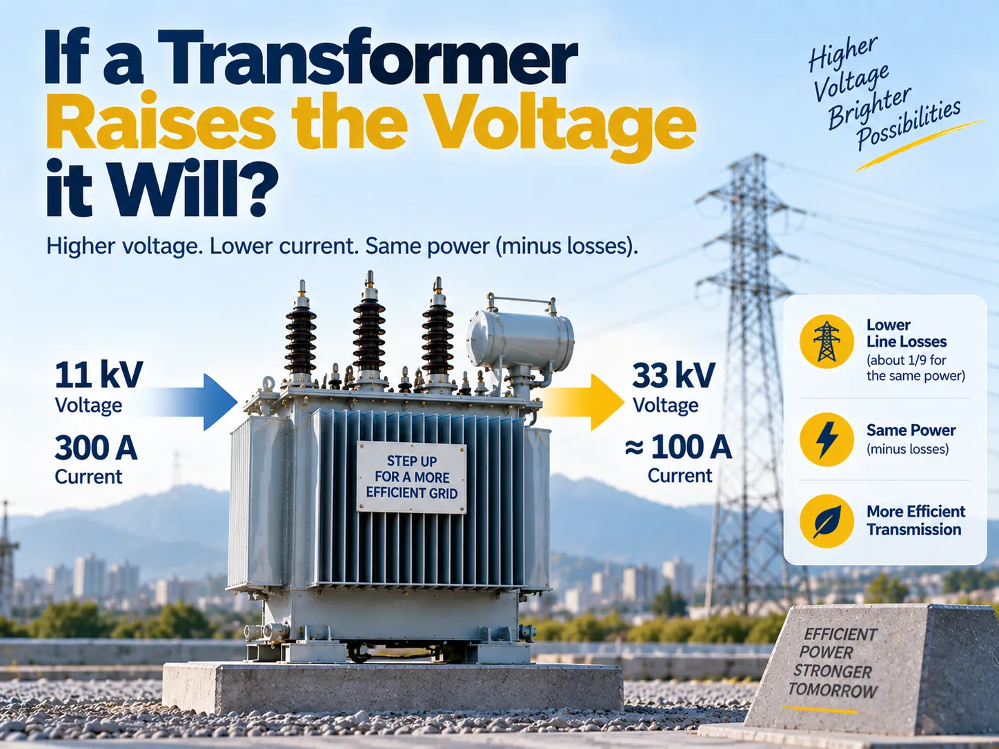
However, one must not forget what transformers cannot do. They cannot change the frequency of the output because the output always has the same frequency as the input. In the same way, transformers cannot generate power because if the output voltage increases, the output current decreases, and hence the output remains equal to the input power (with losses).
The Characteristics That Define Performance
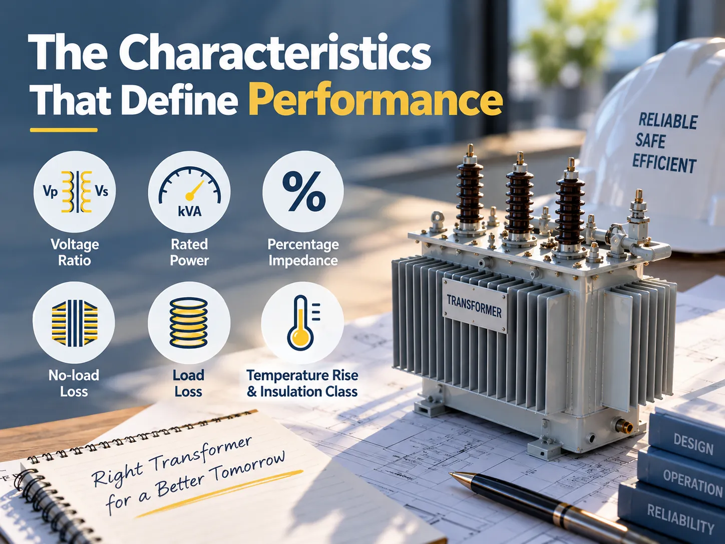
The major differences between the two transformers of equal capacity are based on six factors. Since all the parameters work independently, it is possible to find a transformer that has a low-loss feature with a high regulation characteristic, or a transformer that has a high impedance feature working very satisfactorily.
| Characteristic | What it describes | Typical range | Why a buyer cares |
|---|---|---|---|
| Voltage ratio | Primary to secondary voltage, set by the turns ratio | 11/0.415 kV, 33/11 kV, 132/33 kV | Must match the system, not the load |
| Rated power | Apparent power the unit can deliver continuously | 25 kVA to 1,000 MVA | Sets the load ceiling and the cooling requirement |
| Percentage impedance | Voltage needed to circulate rated current with the secondary shorted | 4 to 6 percent for distribution units | Determines fault current and voltage dip on motor starting |
| No-load loss | Core loss, present whenever the unit is energised | Constant, independent of load | Drives the 24-hour energy bill, even at zero load |
| Load loss | Copper loss, proportional to the square of load current | At rated load, roughly equal to core loss in a well-designed unit | Drives the energy bill at peak |
| Temperature rise and insulation class | Permitted heating above ambient, and the thermal limit of the insulation | 55 K or 65 K winding rise, class A to class H insulation | Sets service life: every 6 to 8 K of extra rise roughly halves insulation life |
Voltage Ratio and Turns Ratio
The turns ratio refers to the number of turns of wire in one winding compared to the number in the other winding. The voltage ratio is the voltage measured at the secondary terminals of the transformer. For an ideal transformer, these two ratios are equal, so we have the relationships primary voltage divided by secondary voltage equals primary turns divided by secondary turns and also equals secondary current divided by primary current; for example for a 1000kVA unit that transforms the voltage from 11 kV down to 415V, the turns ratio becomes approximately 26.5 to 1. The secondary current value becomes approximately 26.5 times that of the primary current at full load.
There are two practical implications to this. Firstly, the design of the two types of windings is very different: the low voltage winding has a large amount of current and is therefore constructed from large conductors, while the high voltage winding has a small amount of current and is constructed from a large number of turns of thin wire. This is why the low voltage side usually governs the physical size of the unit. Secondly, the actual turns ratio is fixed at the factory and can only be changed slightly via tap changing, so it is necessary to confirm the system voltages before an order is placed.
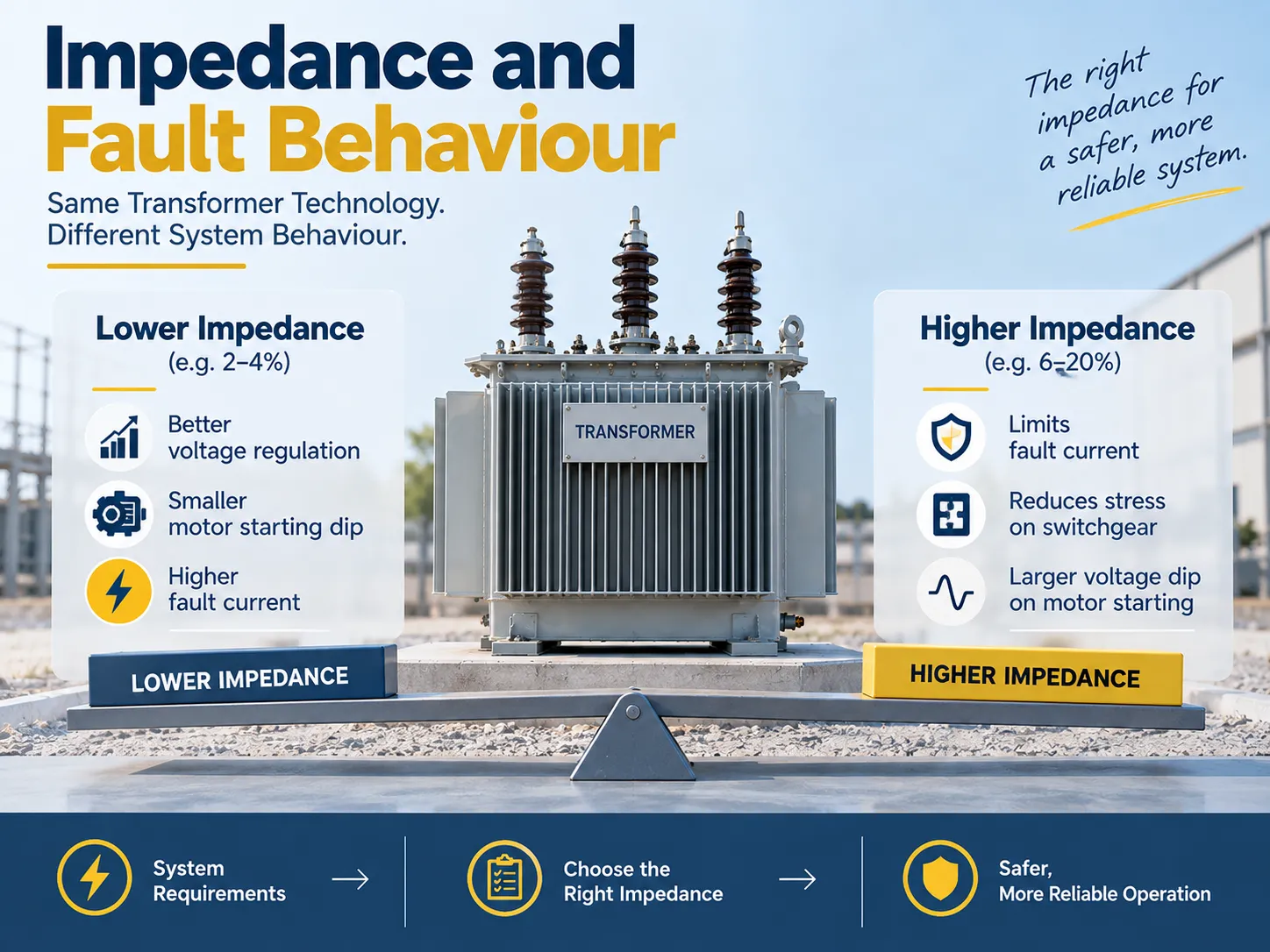
Impedance and Fault Behaviour
The percentage impedance feature is something that buyers often ignore in their purchase decision only to later regret it as the time of need approaches. The way you get the value for percentage impedance is to short circuit the secondary side and raise the primary voltage until you have rated current flowing through the transformer. The voltage, when calculated as a percentage of rated primary voltage at which full load current can be given through the short circuit constitutes the impedance. So when it comes to getting the percentage impedance, the use of the percentage would denote that it takes 5% of rated voltage to drive current.
Impedance designs allow for two contradictory behaviours. On the one hand, a higher impedance would limit fault current, which helps the switchgear and circuit breakers behind it to function better because of the easy fault current they would be fed with. However, a lower impedance allows for a voltage dip to occur when a large motor is energised with high voltages continuously over time. The choice of impedance level thus depends on the design and preference of the operator, given the constraints of the system in question. For example, it is desired to have a lower impedance on inductive motor industrial panels than one feeding a network with the fault level being limiting.
| Transformer class | Typical impedance | Consequence |
|---|---|---|
| Small distribution, up to about 500 kVA | 2 to 4 percent | Good regulation, limited fault limitation |
| Medium distribution, 500 to 2,500 kVA | 4 to 6 percent | The usual compromise on utility networks |
| Large distribution and small power, above 2,500 kVA | 6 to 10 percent | Fault current control starts to dominate |
| Power and transmission transformers | 10 to 20 percent and above | Fault limitation is the primary design driver |
These are indicative bands, not limits. The datum controlling your protective settings will be that indicated on the test certificate for the unit you are using; the practice of paralleling two transformers with different impedances may be self-destructive due to an uneven sharing of the load between the two transformers, which occurs frequently and leads to unexplained overheating of one unit in a pair.
Losses and Real Efficiency
The losses divide into two types that will behave differently. The no-load losses or core losses are due to hysteresis and eddy currents in the iron core and remain constant under load or no load. The load losses or copper losses arise due to the resistance of the windings and increase with the square of the load current or when the transformer is energized even when it is not carrying any load.
This situation results in the surprising situation that the transformer efficiency is not highest at full load. Maximum efficiency occurs at points where both core and copper losses are equal, usually in the range of 50 to 75 % of full load in a distribution transformer. The loss information from testing also allows the purchaser to use an equation that will be more beneficial than comparing transformer efficiencies. This generator can help estimate the actual cost per year for each of the transformers provided by the company based on its load schedule.
As a result of regulations on efficiency, both the levels of efficiency in transformers and core losses have been greatly decreased. The Ecodesign levels in the European Union and the standards proposed by the Department of Energy in the United States are now achieving maximum levels of losses that could not be achieved by older construction designs hence making modern equipment significantly better than transformers older than 15 years just based on no-load losses.
Temperature Rise, Cooling and Insulation
The electrical design is related to the service life by the rise in temperature. The temperature rise is specified as the maximum rise over the ambient temperature at rated load capability, typically at 55 K or 65 K for oil-filled distribution transformers’ windings, with the top-oil rise being somewhat lower. The insulation class is a defining factor for the maximum temperature that the insulation system will withstand, following IEC 60085 classes A at 105 degrees Celsius, B at 130 degrees, F at 155 degrees, and H at 180 degrees.
The actual connection where the economics comes in is through the insulation aging process. Usually, it is estimated that for every 6 – 8 degrees Celsius increase in the operational temperature, the life expectancy of insulation is halved. Thus, a transformer having a specification of 65 K rise and operating continuously at ambient plus 65 will have shorter life expectancy than an identical one rated at 55 K and maintenance will not change the equation. This is the rationale behind the selection of a transformer rated above the operating requirement instead of rated right on it.
It is the method of cooling that is dependent on the type of load and working environment. The oil-filled transformers are referred to by their method of cooling, which may include ONAN for natural circulation of oil and air, ONAF for fan cooled, and OFAF for forced circulation of oil. Dry-type transformers have their own designations according to air cooling such as AN and AF. Manufacturing nameplates can show two ratings, such as ONAN 1,000 kVA and ONAF 1,250 kVA, which means that the higher rating is applicable only when the fans are running.
Regulation and Tap Changing
Voltage regulation measures how much the voltage in the secondary circuit drops when it is loaded, expressed as a percentage. Impedance and the power factor largely dictate the level of voltage regulation. For instance, a transformer with a 4 percent impedance and a nearly unity power factor can be expected to achieve just a few percentage points of voltage regulation, while the same impedance with a lagging power factor higher than 0.8 can produce an alarming voltage drop.
Because the supply voltage and load are constantly varying, tap changers are necessary. Off-load taps, typically plus and minus 5 percent in increments of 2.5 percent, must be set at commissioning to match the supply in that area. On-load tap changers adjust the taps while the transformer is energized and is usually employed on power transformers that must maintain tight tolerances throughout the day. The tap range indicated on the nameplate, such as plus and minus 2 by 2.5 percent, indicates how much voltage regulation is available before engineering changes must be made.
Reading the Rating Plate
The rating plate is a condensed specification and reading it in a prescribed sequence avoids a number of specification mistakes. Below is a table showing what each line commits you to in the specification.
| Nameplate entry | What it fixes |
|---|---|
| Rated power in kVA and cooling designation | Continuous load ceiling, and whether fans or pumps are part of the rating |
| Rated voltages and tapping range | System match and the available voltage correction |
| Rated frequency | Compatibility; a 50 Hz unit on 60 Hz changes impedance, losses and flux density |
| Impedance percentage | Fault level, protection settings and parallel operation |
| Winding temperature rise and insulation class | Service life at rated load |
| No-load and load loss in watts | The energy cost calculation, and compliance with efficiency regulation |
| Insulation level in kV | Withstand capability against switching and lightning impulses |
| Vector group | Phase displacement; paralleling units of different vector groups is not possible |
The vector group should be mentioned specifically, because it is easy to forget and expensive to correct. Even if two transformers have the same capacity and ratio if their vector groups are not the same, they will not operate safely in parallel. These errors will be difficult to rectify at the job site, but the cost will be more expensive than getting it right at tender.
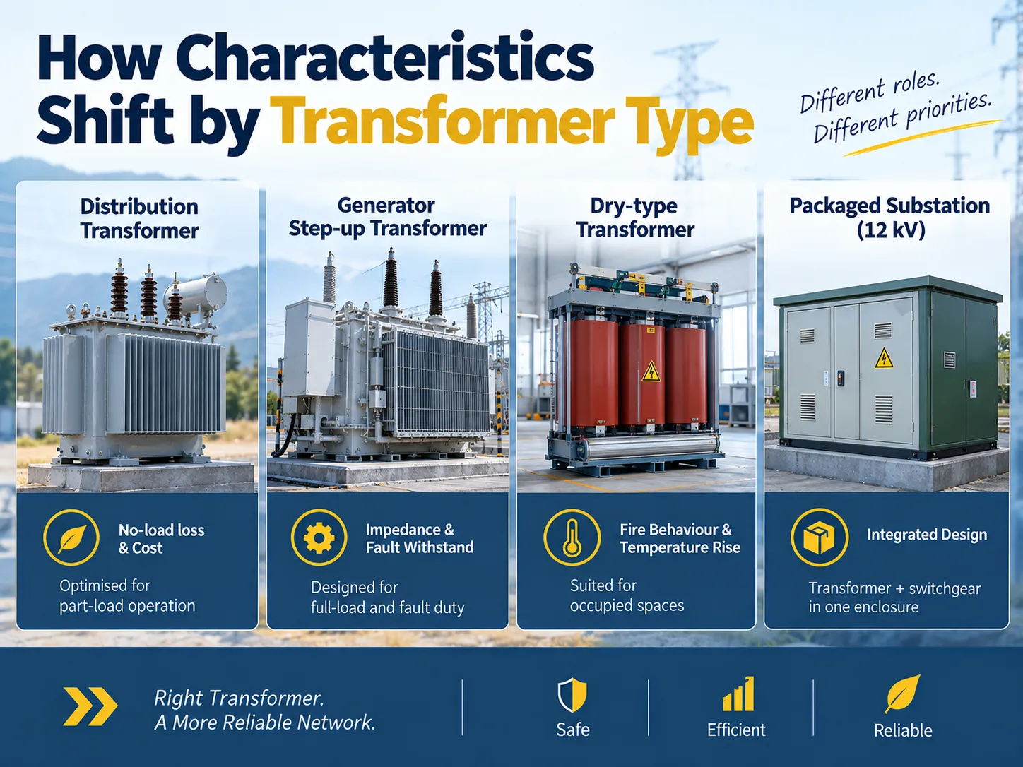
How Characteristics Shift by Transformer Type
Although all the six characteristics above hold true, they may not carry the same weight depending on the position of a transformer in the network. A utility distribution transformer lives and dies with respect to the no-load losses and cost since it spends most of its lifetime at part load. A generator step-up transformer is judged based on impedance, short-circuit withstand and cooling capability since it operates at or near full load and experiences fault duty. A dry-type transformer in a building is selected based on fire safety and temperature rise because that device is inside of occupied spaces.
Packaged units create one more level of complication. A pre-fabricated substation requires the combination of the high-voltage switchgear, the transformer, and the low-voltage switchgear into a single package. Thus, the characteristics of the transformer are important at the interface while the characteristics of the switchgear ratings and the type of packaging level of protection become important for the design.
In the field of equipment for 12 kV distribution, this packaging aspect is where it is easiest to specify incorrectly and where it is easiest to specify correctly. RUY Power manufactures this type of equipment as two main types. The YB□-12/0.4 European-type prefabricated substation covers indoor and outdoor 12 kV distribution from 50 to 1,600 kVA, with the transformer, high-voltage and low-voltage sections designed as one assembly rather than three.
Where the network is overhead-fed and the enclosure has to stand on its own, the ZGS13-H-630/10 combined transformer in the American box-type format packages transformer, fuse protection, metering and low voltage into a single weatherproof unit, with a volume described by the manufacturer as one third to one fifth of a conventional box-type substation of the same capacity. Both families are built to GB/T 17467 and DL/T 537 and tested before despatch.
The full range across voltage levels is listed on our product overview page.
One important factor which is often ignored for packaged substations, without being put off-site, is the increased thermal environment of the transformer. When packed into its enclosure, the transformer will not operate in free air; thus, the air conditioning, or ventilation, as well as the ambient temperature (assumed) has to be figured into the rating calculations. A unit which is capable of operating at 55 K rise in a well-ventilated building may be required to have gas cooling/openings available, or to change its frame if it is placed in a steel box with switch gear during the hot summer season.
FAQ
What are the four main types of transformers?
Defined by their function, there are four types of transformers: step-up transformers that increase voltage for transmission, step-down transformers that decrease it for distribution and usage, isolation transformers that allow power to be transferred at a 1 to 1 ratio to break conductive paths, and autotransformers which have a common winding for primary and secondary to minimize material usage. In term of construction, transformers can be classified into three groups: oil-immersed, dry-type, and sealed or pad-mounted transformers.
What are the 7 transformer types?
There are no standards defining the seven different types of transformers. Rather, the industry and utilities generally group these into 7 categories by application such as generator step-up transformers, transmission power transformers, sub-transmission and distribution transformers, instrument transformers, isolation transformers, autotransformers, and specialty transformers such as those for traction, furnace, and earthing. Recognize that any attempt to list 7 types of transformers infers convenient groupings rather than specific classifications.
What is the most common feature of a transformer?
The one thing all transformers will have in common is their use of a magnetic core linking the primary and secondary windings so that the transfer of energy is through induction without any physical electrical connection between the two circuits. Everything else, such as oil cooling or tap changers, is simply an addition over this basic principle.
What are the three main functions of a transformer?
Transformers serve three functions; to change voltage from one level to another so as to allow economical transmission and distribution, to change the current in inverse proportion so that increasing voltage results in a decrease in current, and to provide galvanic isolation, allowing for power to be exchanged between circuits without conduction.
Does a transformer change frequency?
The output frequency will always remain at the same value as the input frequency; a 50 Hz input will produce a 50 Hz output regardless of the transformer. Thus, transformers are specification-related devices which means that a transformer designed for one frequency will not work for another unless shunt density, losses, or impedance are also checked.
Which characteristic matters most when buying?
It depends upon the situation. When dealing with lightly loaded turning transformers which run continuously, it is the no-load loss and efficiency that will determine the cost of operating the transformer. When one is dealing with motors, the percent impedance and voltage regulation will dictate the nature of or smoothness of the starting process. If one is dealing with transformers in occupied buildings, it is the insulation classes, enclosure types, and temperature rise that will determine viability and safety.
References
- International Electrotechnical Commission — IEC 60076 series, Power transformers, including Part 2 on temperature rise and Part 11 on dry-type transformers
- International Electrotechnical Commission — IEC 60085, Electrical insulation: thermal evaluation and designation
- IEEE Standards Association — IEEE C57.12.00, General requirements for liquid-immersed distribution, power and regulating transformers
- US Department of Energy — Energy conservation standards for distribution transformers
- European Commission — Ecodesign requirements for power and distribution transformers
- US Energy Information Administration — International analysis of electricity generation and grid infrastructure
Conclusion
All varieties of transformer parameters can be determined per violence of the ratio and data sheet parameters but it is possible to derive extra parameters using ratio along with aforementioned parameters.
It is important for someone to realize three things First of all no-load losses for the transformer must be compared in light of the fact that the transformer will be kept on with a light load which is the only situation in which load can be kept and energized Secondly calculating impedance is required for fault conditions at standby mode of operation for starting downstream equipment Finally vector group must be considered in order to make these transformers capable of operating in parallel mode when required because this is irreversible functionality. Following this procedure will ensure that specifications of transformer data plate are not arbitrary.