
All transformers fall into one category. Therefore, they seem to be identical. But this is not correct. Each transformer is a result of various decisions taken regarding a particular application. Even a 1,000 kVA transformer can be designed to be an oil transformer with corrugated tank type to be fitted on a pole, or to be a cast resin transformer to operate in a basement, or be used as a pad mounted transformer in its natural setting.
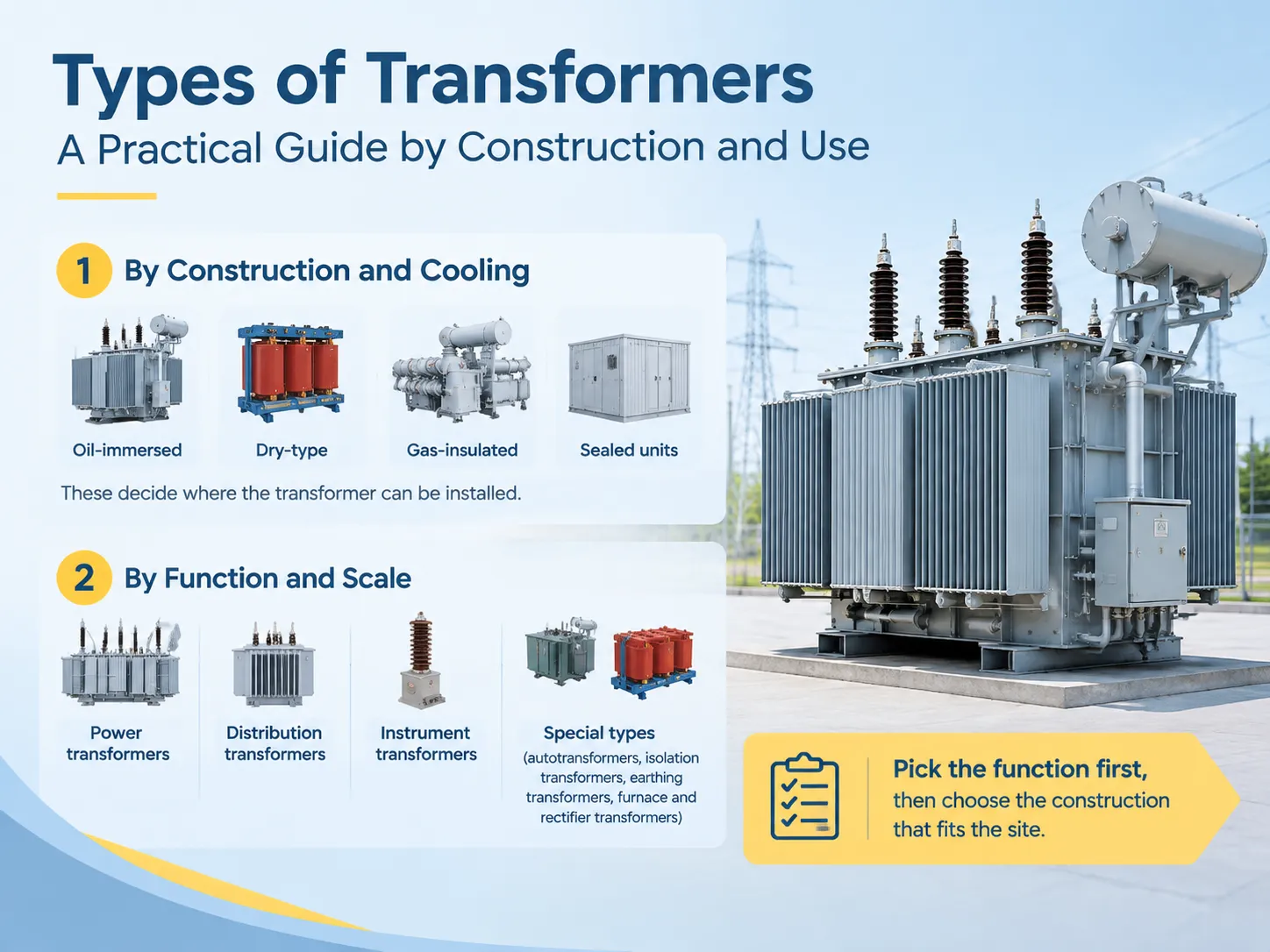
Concise response: There are two kinds of transformer classification. From the point of construction and heat dissipation, transformers can be oil-cooled, air-cooled or gas-cooled depending on where they will be placed. Additionally, transformers can also be classified by their size and operational purpose: power transformers used for transmission, distribution transformers, measuring transformers etc. The classification is needed to be determined according to the purpose first and then the correct construction type should be identified according to the location.
Two Classification Axes, Not One
Each transformer deals with two questions at its outset. Firstly, what function does the transformer perform in the system: whether it works for bulk power transmission, customer distribution, signal measurement, or something specific such as earthing and rectifying? Secondly, how is it constructed: whether it is oil-insulated or dry, sealed or allowing breathing, pole-mounted or placed on pads or inside walls?
The confusion between the two provides most bad specifications on the market. A customer asks for a “distribution transformer,” but he/she ends up with something suited technically for the network but impossible to be installed, due to the fact that nobody thought about the second question. The table below allows separating the two axes to present them in the correct order.
| Axis | Question it answers | Options |
|---|---|---|
| Function and scale | What is it for, and how big is it? | Power, distribution, instrument, special purpose |
| Construction and cooling | Where can it be installed, and how is heat removed? | Oil-immersed, dry-type, gas-insulated, sealed or with conservator |
| Installation format | How does it sit on site? | Pole-mounted, pad-mounted, plinth-mounted indoor, packaged substation, mobile |
| Phase arrangement | How many phases does it serve? | Single-phase or three-phase, with the vector group that follows |
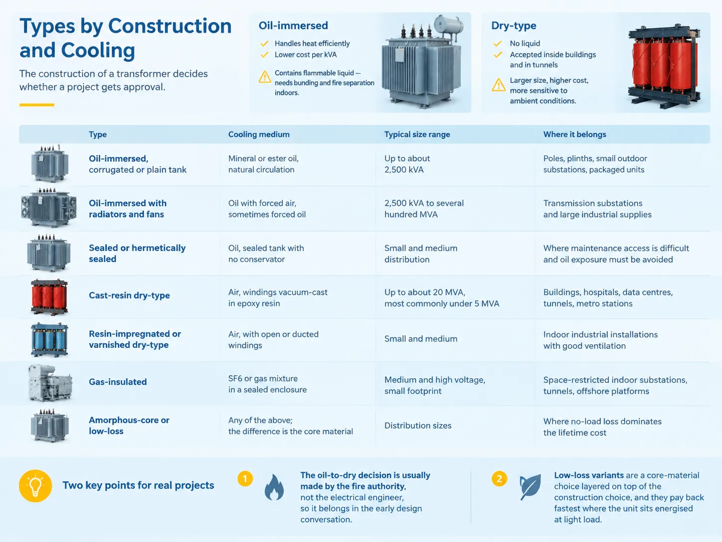
Types by Construction and Cooling
Building bridges is the factor determining if the whole project gets green light. Oil immersed transformers have great heat dissipation and lower price in kVA but they are made of a combustible liquid which makes building bunding and fire separation indoors a must. Dry-type transformers eliminate the liquid which allows them to be used indoors and in tunnels but they are prone to size increase, changeing expenses and vulnerability to ambient conditions.
| Type | Cooling medium | Typical size range | Where it belongs |
|---|---|---|---|
| Oil-immersed, corrugated or plain tank | Mineral or ester oil, natural circulation | Up to about 2,500 kVA | Poles, plinths, small outdoor substations, packaged units |
| Oil-immersed with radiators and fans | Oil with forced air, sometimes forced oil | 2,500 kVA to several hundred MVA | Transmission substations and large industrial supplies |
| Sealed or hermetically sealed | Oil, sealed tank with no conservator | Small and medium distribution | Where maintenance access is difficult and oil exposure must be avoided |
| Cast-resin dry-type | Air, windings vacuum-cast in epoxy resin | Up to about 20 MVA, most commonly under 5 MVA | Buildings, hospitals, data centres, tunnels, metro stations |
| Resin-impregnated or varnished dry-type | Air, with open or ducted windings | Small and medium | Indoor industrial installations with good ventilation |
| Gas-insulated | SF6 or gas mixture in a sealed enclosure | Medium and high voltage, small footprint | Space-restricted indoor substations, tunnels, offshore platforms |
| Amorphous-core or low-loss | Any of the above; the difference is the core material | Distribution sizes | Where no-load loss dominates the lifetime cost |
Two crucial aspects of that table stimulate concrete works. One is that it is the fire authority, rather than the electrical engineer, which regularly makes the oil-to-air decision, thus making such decision part of the early design discussions. The second aspect is that low-loss versions are not types of their own but rather materials that are to be used on the top of the construction material choice, hence they are efficient in operation when the unit is in operation but experiences low load.
Types by Function and Scale
The functional classification adheres to the voltage hierarchy of the system. Each step emerges as it becomes economic to distribute energy at a different voltage.
| Function | Typical capacity | Typical voltage | What it does |
|---|---|---|---|
| Generator step-up transformer | 100 MVA to over 1,000 MVA | Up to 400 kV and above | Raises generator output to transmission voltage |
| Power transformer | Above about 10 MVA | High and extra-high voltage | Links transmission systems and large industrial loads |
| Sub-transmission transformer | 10 to 100 MVA | Usually 132/33 kV class | Steps transmission voltage down to regional distribution |
| Distribution transformer | 25 kVA to 2,500 kVA | Usually 11, 33 kV or 12 kV to 415 V | Serves the final step down to utilisation voltage |
| Instrument transformer | Small, rated in VA burden | Any system voltage | Scales current or voltage down for measurement and protection |
| Special-purpose transformer | Wide range | Application specific | Furnace, rectifier, traction, earthing, welding duties |
The commercial division between a distribution and a power transformer is not an international norm. It is a norm which is set close to 10 MVA, but companies do it differently. What does not change is the design implication. Power transformers are designed specially for one project only, have to be tested according to demanding specification, and last for a long time. Distribution transformers are standard devices which are bought in large quantities.
Instrument Transformers
Instrument transformers have been made so that the devices that depend on the transformers never come into contact with the high-voltage part of the network. In a similar manner, the current transformer diminishes the high primary current transferring it to the secondary current of 1 A or 5 A, and the voltage transformer decreases the voltage of the whole system close to 110 V. Although both accomplish the same work as any transformer does, they are selected in terms of the accuracy class, burden, and rated output instead of their power rating.
The reason why they are commercially important is that these devices are usually acquired independently and regarded as additional ones. If a current transformer does not have an appropriate accuracy class, burden, or knee-point voltage, the protection system will work slower and/or inaccurately. Since the instrument transformers are mounted into the switchgear, the only option in case of replacing them is to shut down the whole switchgear and install new transformers. The standard accuracy class for the cores used for protection is class P, class 0.5 for metering ones. Besides, it is important that the secondary circuit is never kept open while primary current is passing through it.
Autotransformers, Isolation and Special Types
Autotransformers have the advantage of using a single winding with a tapping point at one or more locations along its length, and hence, the autotransformer winding carries both primary and secondary currents. This means that cores and wires used in autotransformers are less in quantity than other regular transformers. However, this also means that the two circuits do not have electrical isolation. Autotransformers find applications in voltage regulation and in long transmission lines where voltage transformation ratio is close to unity. However, they do not find applications where isolation is required.
Isolation transformer is a special type of transformer that employs 1:1 transformation ratio so that the conductive path can be further isolated by using this kind of transformer. Typically, isolation transformers have screens earthed between their windings to reduce the capacitive coupling effect. They are commonly used in hospitals, testing laboratories, and the applications where shocks may be caused to the users.
Different types of transformers are developed for specific needs of a load. Furnace transformer provides very high amount of current and solves the issue of getting short-circuited. Rectifier transformer feeds a converter and works with direct current and harmonic components. Traction transformer has to fit under train and work with frequent changes of load. The grounding transformer is also needed for systems without neutral point for fault detection.
Single-Phase and Three-Phase
Single-phase transformers are utilized in residential distribution in some systems, especially in North America where they are placed on poles, as well as in small loads and in remote locations in the rest of the world. The majority of the capacity throughout the world is linked to three-phase transformers. The difference is a mechanical one as well as electrical: three units of single-phase transformer can be replaced one by one and lifted with hands or by a small crane, on the other hand, one three-phase equipment is smaller in size, is less expensive within the same capacity but cannot be replaced in thirds.
This choice also impacts the vector group. The three-phase transformer has a predetermined position between primary and secondary, for instance Dyn11 on a distribution device, and that marking should be the same to be able to connect the units in parallel.
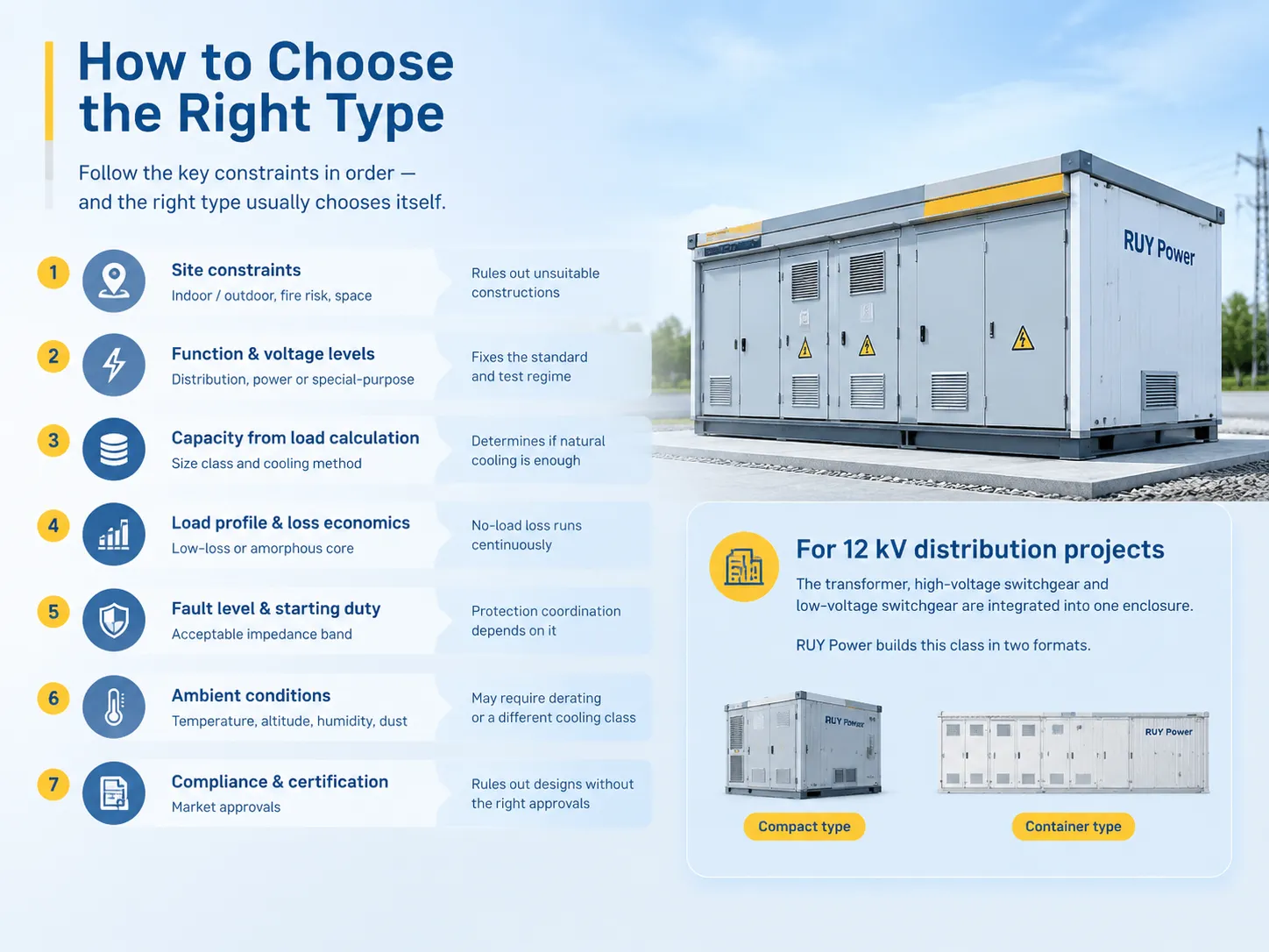
How to Choose the Right Type
Decision-making becomes simple once the limitations are gathered properly. Follow the following list of objects and one mostly knows about its kind in advance.
| Decision | What it rules out | Why it comes first |
|---|---|---|
| Site constraints: indoor, outdoor, fire risk, space | Rules out oil-immersed indoors; rules out large dry-type where space is tight | These constraints cannot be solved by re-rating the transformer |
| Function and voltage levels | Fixes whether you need a distribution, power or special-purpose design | The standard and the test regime follow from it |
| Capacity from the load calculation | Sets the size class and cooling method | Determines whether natural cooling is enough |
| Load profile and loss economics | Decides whether low-loss or amorphous core pays back | No-load loss runs continuously regardless of load |
| Fault level and starting duty | Fixes the acceptable impedance band | Protection coordination depends on it |
| Ambient conditions: temperature, altitude, humidity, dust | May require derating or a different cooling class | The rating plate assumes standard conditions |
| Compliance and certification for the market | Rules out designs without the right approvals | Retrofit certification is rarely possible |
A good conveyor of success in 12 kV distribution applications would often provide the solution already in a ready-made form, as transformer, high-voltage circuit breaker and low-voltage breaker are already combined in a one “box”.RUY Power builds this class in two formats. The YB□-12/0.4 European-type prefabricated substation covers 50 to 1,600 kVA for indoor and outdoor urban networks.
The ZGS13-H-630/10 American box-type combined transformer packages transformer, fuse protection, metering and low voltage in a single compact unit for overhead distribution, which is the usual choice where there is no switchroom to build.
The complete range across high, medium and low voltage is on the products page.
Comparison Table
| Type | Footprint | Relative cost at same rating | Best fit |
|---|---|---|---|
| Oil-immersed sealed | Compact | Lowest | Outdoor distribution, packaged substations |
| Oil-immersed with radiators | Large | Low to moderate | Substations with access for maintenance |
| Cast-resin dry-type | Larger, especially in height | Higher | Indoor installations where a flammable liquid is not acceptable |
| Gas-insulated | Very compact | Highest | Space-restricted medium and high voltage rooms |
| Autotransformer | Compact | Lower than an isolating unit of similar ratio | Voltage correction and close-ratio interconnection |
| Instrument transformer | Very small | Low, but accuracy dependent | Metering and protection inside switchgear |
FAQ
What is a type 3 transformer?
There is no universal classification known as a “type 3 transformer”. In transformer terminology, type 3 frequently signifies an enclosure rated as a NEMA 250 type 3 compartment, which enables it to be weather-resilient in the event of rain, sleet and snow. Consequently, a dry-type transformer assembled in that enclosure may also be referred to in a vague manner as a type 3 transformer. If this term appears in a specification, it is important to clarify which standard is being used since it can affect specifications significantly.
What are the three main types of transformers used in industry?
There are three major families of transformers in industrial applications: distribution transformers which convert incoming voltages to operational values, dry-type transformers used in premises that do not allow oils to be used in the transformers, and special transformers like converter transformers, furnace transformers or earthing transformers that serve for particular usages. Measuring transformers have been located in switchgears for the purpose of measuring the voltage.
What type of transformer is used in residential areas?
Residential areas use small oil-type distribution transformers, usually rated from 25 to 500 kVA, that can be either pole-mounted or installed in a package or in a pad-mounted enclosure and that lower medium voltage to supply residential voltage. Dry-type transformers or gas-insulated transformers are preferred over oil-type ones in places where oil transformers cannot be used.
What is HV, LV and IV in transformers?
HV stands for high voltage and LV stands for low voltage, which are commonly used terms to define windings of high voltage (11 kV) and low voltage (415 V). The term MV (medium voltage) refers to voltages that typically vary between 1 kV and 36 kV. The term IV is not associated with any particular type of transformer; the only instances when one may come across this abbreviation is in the context of the quality of power.
How many types of transformer are there in total?
The total number of transformer types is indeterminate. The reason for this is that types can be classified by various parameters like purpose, cooling medium, installation, phase connection and core design. This means that some single unit can belong to several categories at once, being a dry-type, oil-type, three-phase and pad-mounted transformer that is characterized by amorphous core design as well.
References
- International Electrotechnical Commission — IEC 60076 series, Power transformers, and IEC 60076-11 for dry-type transformers
- International Electrotechnical Commission — IEC 61869 series, Instrument transformers
- IEEE Standards Association — IEEE C57.12.00 and C57.12.01, general requirements for liquid-immersed and dry-type transformers
- NEMA — NEMA 250, Enclosures for Electrical Equipment
- NFPA — NFPA 70, National Electrical Code, provisions covering transformer installation
- US Department of Energy — Distribution transformer efficiency standards and grid equipment resources
Conclusion
Upon examining the varieties of transformers, it is better to respond to queries about the required transformer type and the site suitability. In light of some known working principles, it should be easy to answer the question as to whether this transformer in mind will be a power transformer or a distribution transformer, etc. Awareness of the transformer construction methods will prove useful. The type of transformer can be determined by the construction techniques. In some cases, fire safety legislation is more important than electrical parameters.
When it comes to making the decision, three points must be remembered. First, make the choice of the site first of all before doing any comparison due to the fact that the least expensive option may not be allowed. Second, consider using the models of transformers featuring low losses or those of the amorphous core brand type if it’s planned that the transformer will be used on a temporary basis. Last but not least, do not restrict your comparison of transformers to the cases when the decision regarding electrical equipment purchase is to be taken.