
The apparatus is nearly always introduced in an incomplete manner because the exciting bits of information are always found after the apparatus. It’s necessary to drop something elsewhere after a transformer has raised the voltage since a transformer cannot supply electricity. The explanation is found at the center of each transmission and delivery decision taken, as it explains why electricity travels through countries at hundreds of kilovolts and reaches your meter with some hundred volts.
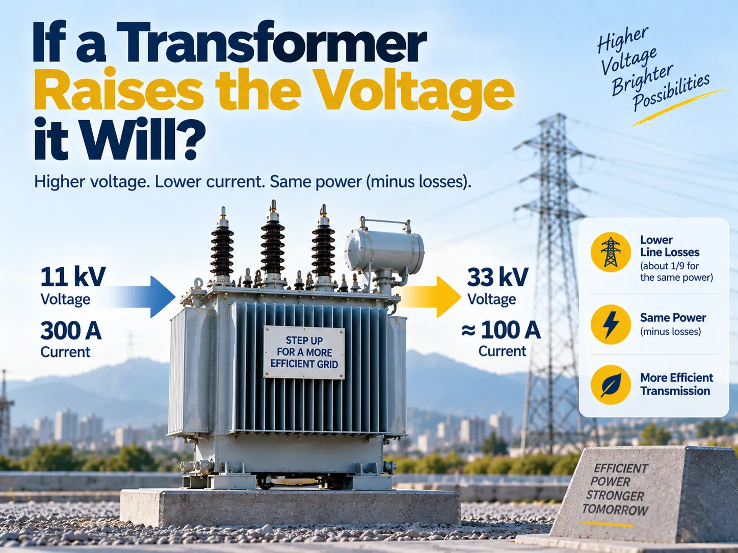
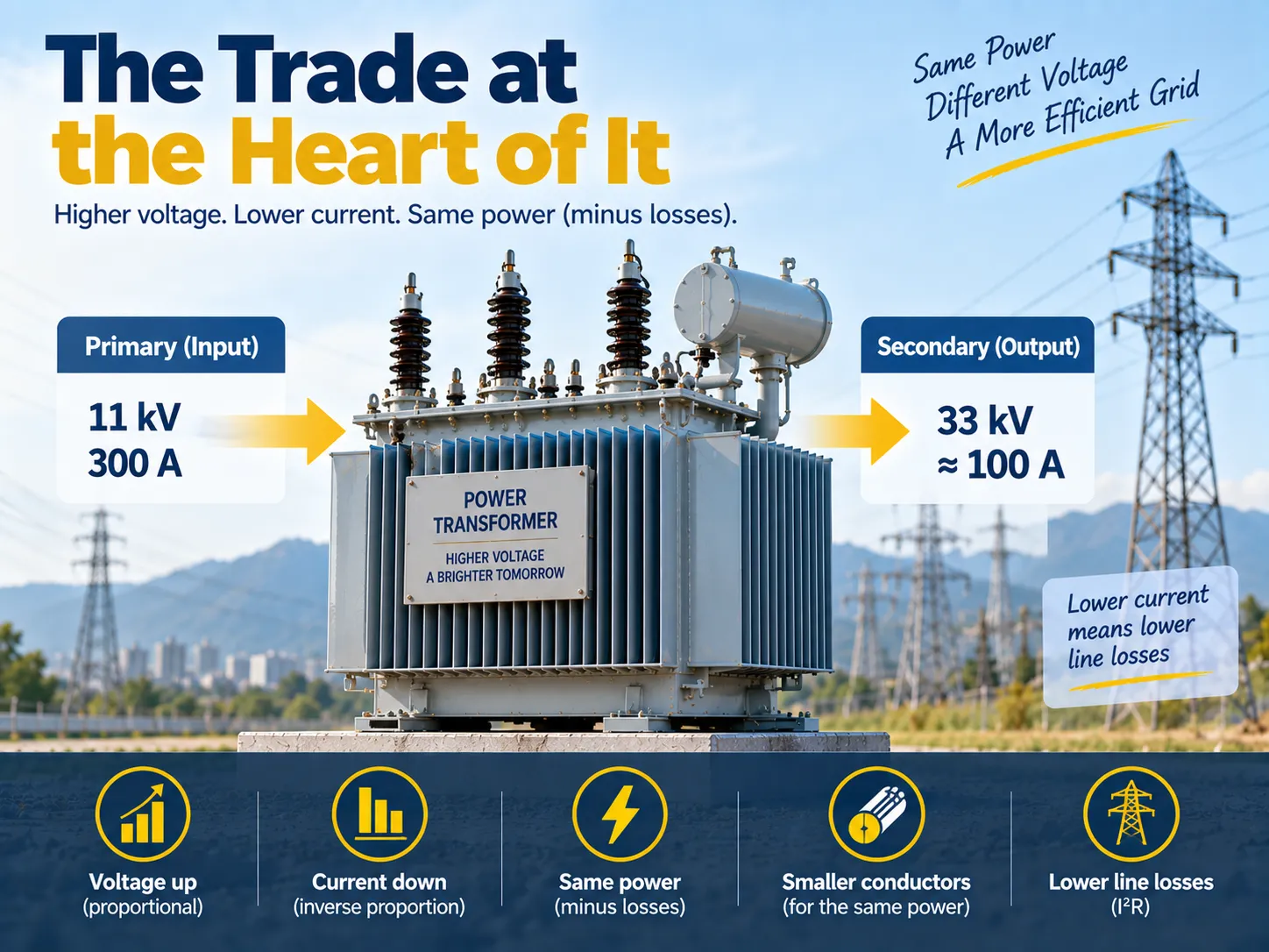
The basic idea is: when a transformer increases voltage, it almost reduces current at the same rate with the total amount of power remaining virtually unchanged (taking into account losses). For example, a transformer changing voltage from 11 kV to 33 kV increases voltage 3 times, while the current is reduced to about a third of its initial value. This is the whole purpose of stepping up: losses in the line increase with the square of current, so cutting down current three times reduces losses in the wire roughly N times for the same delivered power.
The Trade at the Heart of It
Perfect transformers transmit apparent power without changes, and this gives us the way to compute it, which is being known by every electrical engineer: primary voltage multiplied by primary current equals secondary voltage multiplied by secondary current. Increasing secondary voltage will cause the secondary current to drop in the same proportion, for example, increasing it tenfold will cause the decrease of ten times for the current.
An actual transformer causes some losses in the process, meaning the output will be less than input power, which leads to the fact that current will be a bit higher than was predicted. But everything related to the process is still not influenced by the losses.
| Quantity | Effect of stepping voltage up | Reason |
|---|---|---|
| Voltage | Rises in proportion to the turns ratio | Induced voltage per turn is the same in both windings |
| Current | Falls in almost the same proportion | Apparent power is preserved, minus losses |
| Apparent power | Essentially unchanged | A transformer cannot generate power |
| Conductor size for the same power | Falls on the high-voltage side | Lower current needs less copper or aluminium |
| Insulation requirement | Rises sharply | Clearances and insulation levels follow voltage |
| Line losses for the same power | Falls with the square of the current reduction | Loss in a conductor equals current squared times resistance |
Why Anyone Steps Voltage Up
Losses in a conductor are equal to the square of the current multiplied by the resistance. This equation explains practically the whole system of the electricity supply industry. To transmit 1 megawatt through a wire one must transmit it at 11 kV having approximately 52 amperes per phase or at 132 kV having approximately 4.4 amperes per phase. The resistance of the conductor remains constant and the current drops by 12 times which means that the losses drop by 144 times.
In the opposite example we keep the same loss but reduce the size of the conductor which actually happens in practice. High-voltage transmission lines are built due to the necessity of huge sizes of the conductors if the power is transmitted at the low voltage and due to impossible maintenance of the weight of towers or due to the fact that these metals cost much more than the power supplied.
The same works in reverse at the service point. Distribution transformers bring down 11 kV or 33 kV voltage to 415 or 240 volts because it is too difficult to work with the insulation of high voltage in the buildings but currents of low voltage can be handled over small distances. In reality the network consists of the stages of trades with voltage in accordance with the changing economics.
How the Transformer Does It
A laminated steel core is shared by two coils. By the virtue of alternating current in the primary coil, a changing magnetic flux is produced, which passes through the secondary coil, causing induction of voltage. The same magnetic field passes through all the turns of both coils, making the induction of voltage per turn equal in both coils; therefore, the voltages at the terminals of both coils are proportional to the number of turns.
The only difference between an ordinary transformer and a step-up transformer is the number of turns in the secondary coil, which is greater than in the primary coil. There is no amplifier, no moving parts and no energy in stock. The coils are insulated from each other, which is an additional advantage of using a transformer.
This mechanism allows for two conclusions to be drawn immediately. The frequency is preserved because of the fact that the induced voltage works according to the frequency of the provided voltage. Besides, the voltage ratio is predetermined by the design of the transformer and can be adjusted only within the limits of the tap changing system.
A Worked Example
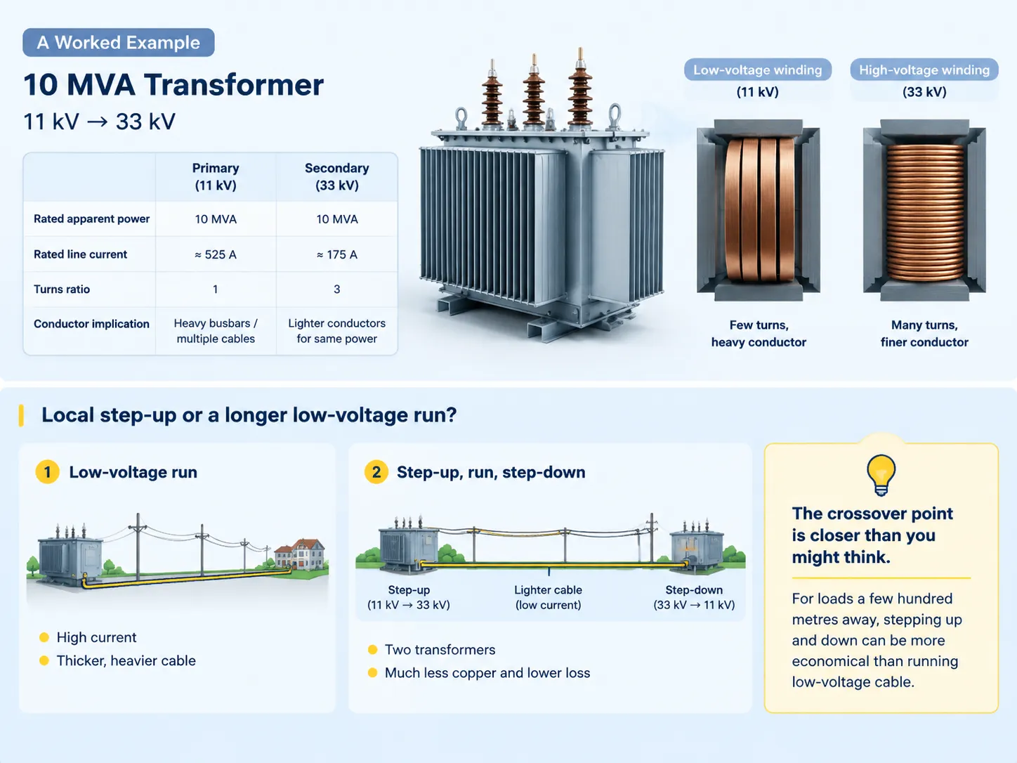
Consider a transformer with a capacity of 10 MVA, which increases voltage from 11 kV to 33kV. The rated currents are ascertained based on the standard relationship of three-phase system in which the apparent power is divided by the product of root three and line voltage.
| Quantity | Primary side, 11 kV | Secondary side, 33 kV |
|---|---|---|
| Rated apparent power | 10 MVA | 10 MVA |
| Rated line current | About 525 A | About 175 A |
| Turns ratio | 1 | 3 |
| Typical conductor cross-section implication | Heavy busbars or multiple parallel cables | Substantially lighter conductors for the same power |
Making the calculations manually is worthwhile at least once since it shows the design consequences. The high-voltage windings need more turns of thin wire and a larger insulator clearance, whereas the low-voltage winding needs far fewer turns of thicker wire and a more modest clearance requirement. Thus, a transformer is not symmetrical, with the two ends being totally different in appearance and cost.
The same principle applies here in the case of choosing more local step-ups and longer runs of low-voltage cables. If a project has to install a load several hundred meters away from the source of power, one has to decide whether to run low-voltage cables at high ampacity or to raise the voltage, send lighter wire at low ampage, and then reduce the voltage at the far end. The second option means that two transformers are required, but a huge amount of copper as well as losses is avoided, and the point of crossing is usually much closer that most people would expect.
What Changes Besides the Numbers
There are more than two readings changed on the meter when increasing voltage. Insulation levels and clearances needs to go up bringing about the change in dimensions and cost of bushings, tanks, cable terminations and switchgear in use. Moreover, short circuit current reactions will have another behavior due to impedance seen on one side of circuit being proportional to the square of the turns ratio between two sides. Historically, setting of the relay and calculation of the protection coordination have not been changed.
Voltage regulation is also becoming visible. The percentage regulation of the transformer is mainly determined by its impedance and the load power factor, but the situation is different with the transformer regulating power feeding a long line, because line impedance is added to the transformer impedance.
Step-Up and Step-Down Are the Same Machine
The terminology refers to the purpose of the winding and not its construction. In other words, it does not matter which winding is used for input as long as its insulation and tap range are suitable for appropriate voltages. Reverse feeding of distribution transformers is a standard procedure. It is typically safe but not always advisable because there are some designs where the tap winding is located on the high-voltage side and some different protection methods versus power flow direction are possible.
This difference is important now more than ever. Solar panels and battery storage are capable of sending electricity back through the distribution transformers that were designed to handle the electricity flowing in one direction which changes load profile, raises voltage at the connection point and, in some cases, makes a transformer be loaded in an unexpected manner. Therefore, when the electrical supply company receives complaints regarding voltage rise due to solar installations, the transformer design and tap position should be analyzed.
Where Stepping Up Stops Paying
While it is true that increasing the voltage reduces the loss, what keeps us from using the highest voltage possible? The answer is simple. The costs associated with insulation, clearance, and equipment increase faster than the reduction in losses once a transmission line has reached the adequate network size. At short distances, losses from using high-voltage switches and transformers outweigh the cost of the additional equipment.
However, there is also a physical limit for the use of very high voltages. At some point, air becomes the limiting factor, so the only practical solution for long-distance submarine and intercontinental connections has been the use of direct current. This way, high-voltage direct current is used for transmission, with converter transformers located at both ends to convert AC to DC. Direct current transmission solves all issues related to the use of alternating current, which is why the longest electricity connections are current as HVDC rather than alternating current.
Causes of Unexpectedly High Voltage
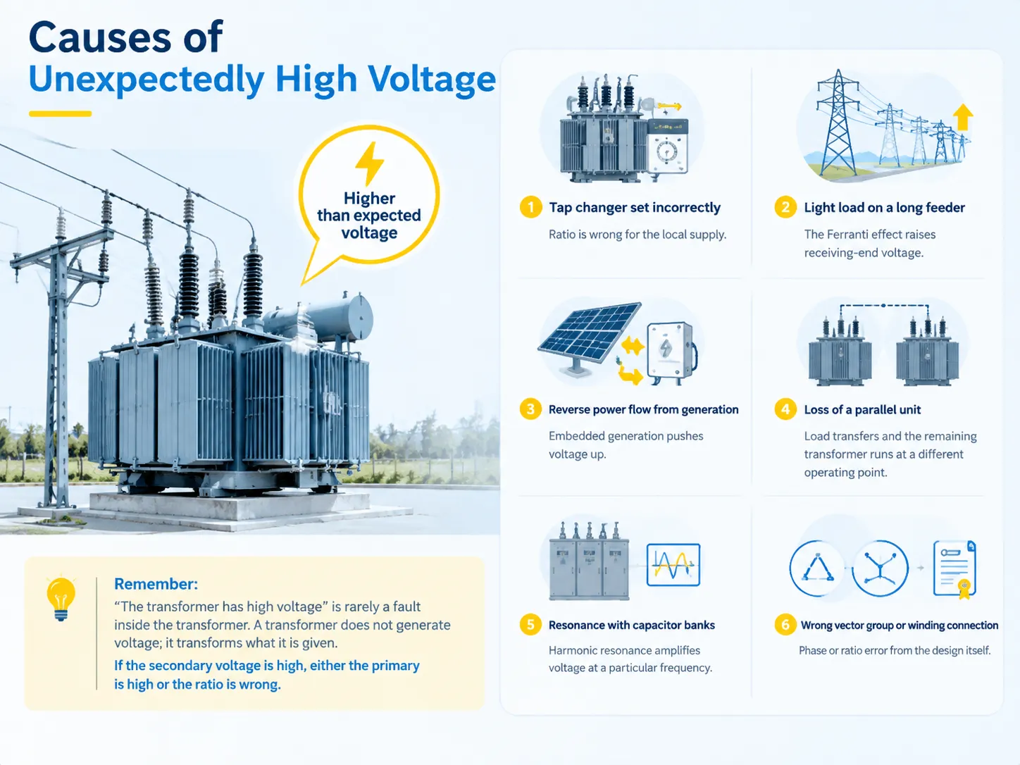
When voltage is found to be greater than anticipated at a location, it normally results from one of a few causes, thus it is recommended to distinguish between causes originating from transformers from those that cause system failure prior to making any replacements.
| Cause | What is happening | Where to look |
|---|---|---|
| Tap changer set incorrectly | Ratio is wrong for the local supply | Tap position and the commissioning record |
| Light load on a long feeder | The Ferranti effect raises receiving-end voltage above sending-end | Load profile and feeder charging current |
| Reverse power flow from generation | Embedded generation pushes voltage up at the point of connection | Inverter settings and the transformer tap |
| Loss of a parallel unit | Load transfers and the remaining transformer runs at a different operating point | Paralleling arrangement and impedance match |
| Resonance with capacitor banks | Harmonic resonance amplifies voltage at a particular frequency | Power factor correction and harmonic survey |
| Wrong vector group or winding connection | Phase or ratio error from the design itself | Nameplate, test certificate and connection diagram |
It should be understood that “high voltage in the transformer” is seldom a fault of the transformer. Why? Because the voltage is not created by a transformer, it is transformed. A non-technical person may think that if the secondary voltage is high, the transformer must be supplied with high primary voltage. However, it may also happen that the voltage ratio is incorrect.
In the case of packaged distributing switchgear it is important to specify the voltage ratio during preparations of the equipment. RUY Power builds 12 kV distribution units in the YB□-12/0.4 prefabricated substation format for indoor and outdoor networks, available across a 50 to 1,600 kVA range.
The ZGS13-H-630/10 combined transformer covers the American box-type format for overhead-fed networks, where the same ratio decision applies to a different enclosure and a different set of fuse and metering arrangements.
Both are configured to the system voltage rather than adapted to it after delivery, and the full range across high, medium and low voltage is listed on the products page.
FAQ
How does a transformer increase the voltage?
The voltage is raised in a transformer by increasing the number of turns of wire on its secondary coil as compared with the primary coil. The alternating current from the primary coil produces an alternating magnetic flux in the core of the transformer, and the flux induces voltage in all the turns of wire of the transformer. Since the induced voltage per turn of the wire is the same for all turns, having a larger number of turns of wire means getting a higher voltage across the terminals of the transformer.
What happens if the voltage increases?
In response, the current will also decrease almost by the same ratio so that the power remains the same. The higher voltage at the output of the transformer means less energy dissipation and higher requirements towards insulation. At the same time, the increase in the voltage applied to the transformer will also help to increase magnetic flux density, therefore, the losses and heating inside an electric transformer.
Does a step-up transformer increase power?
No, power out will always be less than power in due to power losses. The step-up transformer raises the necessary voltage and decreases current but the apparent power remains approximately the same.
Why is voltage stepped up for transmission?
As for electrical loss it occurs due to the product of current squared by resistance value. Increasing voltage decreases current of load and therefore loss will be smaller due to squared decrease. It quite happens to use heavy wires with low voltage values, but it is more expensive compared to using transformers and protection.
What would cause a transformer to have high voltage?
Usually, there are other factors such as wrong tap changer setting, lightly loaded line with Ferranti effect, reverse current from generators, lost parallel transformer, and resonance effect with capacitor banks. In general, the transformer changes voltage value but it does not create it.
How does a transformer affect voltage?
It scales the voltage with the help of turns ratio and slightly reduces voltage due to impedance when the transformer is loaded. The second effect is known as voltage regulation which varies a few excess percent when comparing loaded and unloaded transformer and makes the load voltage lower in case of loaded transformer.
References
- International Electrotechnical Commission — IEC 60076 series, Power transformers
- IEEE Standards Association — IEEE C57.12.00, General requirements for liquid-immersed transformers
- US Department of Energy — Transmission and distribution infrastructure and grid loss resources
- US Energy Information Administration — Electricity transmission and distribution data
- International Electrotechnical Commission — IEC 61378 series, Converter transformers for HVDC applications
Conclusion
Increasing voltage causes decreased current of almost the same degree, and in effect, there is almost no change in power as well, apart from the losses. This is not a side effect of the design; rather, this is what makes this design possible. Line losses are proportional to the current squared, and using voltage instead of current is the cheapest option in terms of transmitting power over distances.
There are three points of utmost importance in practical terms. This ratio is set by the turns ratio, and one cannot change it after the transformer has been manufactured, except for changing taps. The fact that the voltage has been increased affects not only the transformer itself but surrounding devices, since insulation and clearance parameters depend on voltage as well. What is more, the device operates in the reverse mode if it receives power from another side, which is basically what happens when power produced by dispersed generation is returned to the grid.
Therefore, in the specification, to ensure that the insulation level and the ratio are correct is instrumental in ensuring that the entire system would rest firmly on the foundation.