
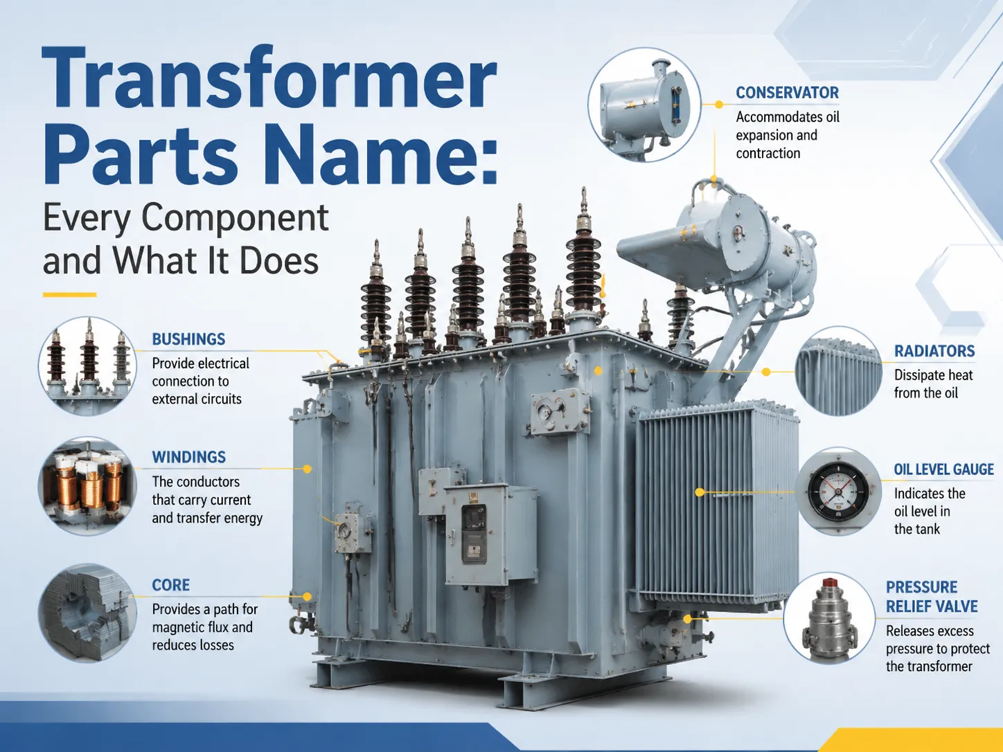
When you open up a transformer’s specs, you’ll see terminology that presumes you have previous familiarity with the equipment: conservator, Buchholz relay, bushing, tap changer, active part, etc. For when the elements are discussed in the order of their function, and knowing the terms is commercially important as, again, each will appear as a line in a quotation, and as a question in a factory acceptance test.
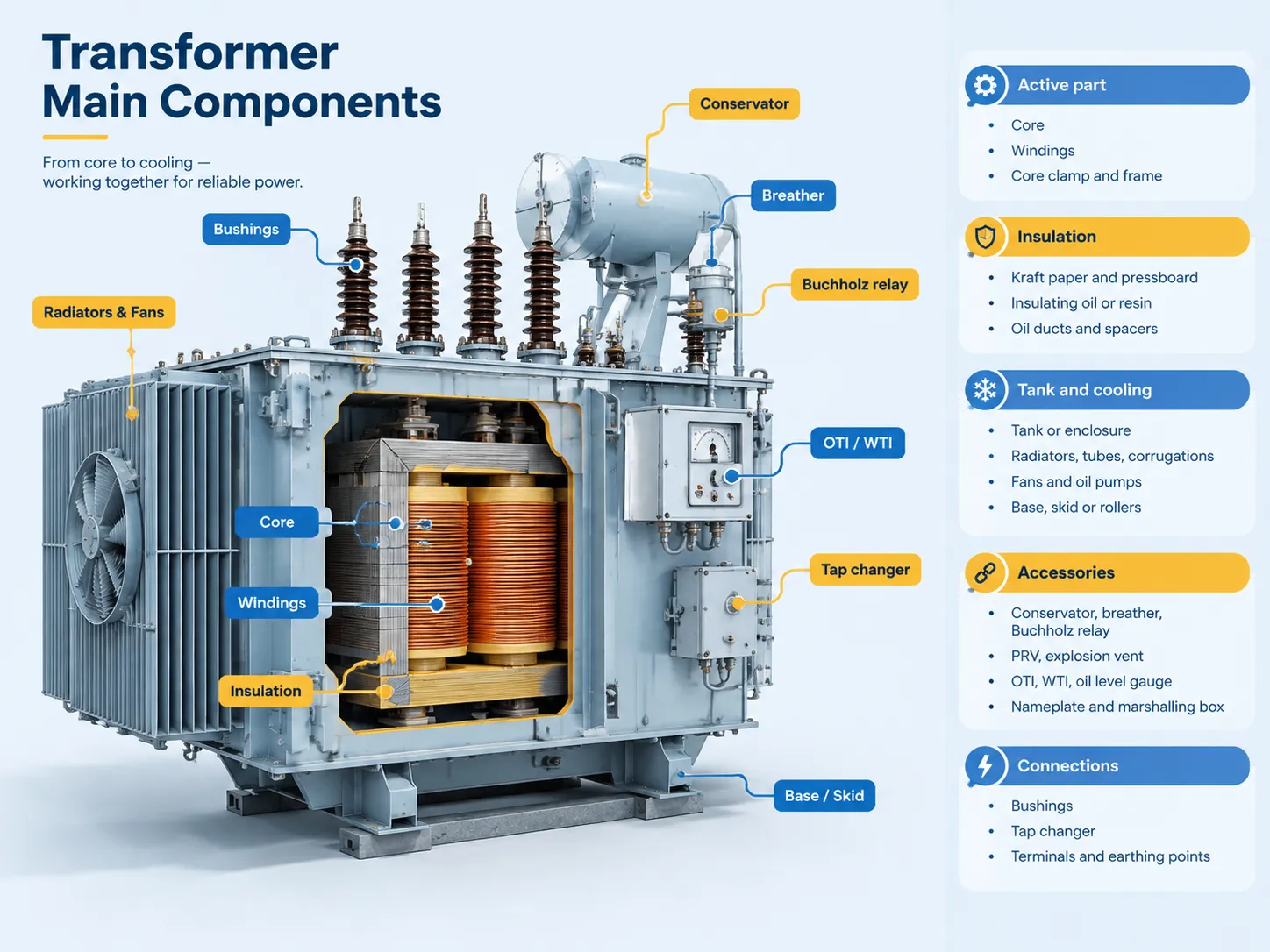
A transformer has four components. The active component consists of the core and the windings which are actually doing the conversion of energy. There are the insulation components which are comprising of paper, pressboard, and oils or resins which keep the windings separate electrically and dispose of heat. The tank contains the assembling structures or enclosure, radiators or walls, cooling groups, and fans, and pumps used for disposal of heat. The accessories are involved in the operation of the parts of the device, which includes bushing, tap changer, conservator, breather, Buchholz relay, pressure relief valve, oil level gauge, and temperature measuring devices.
The Active Part: Core and Windings
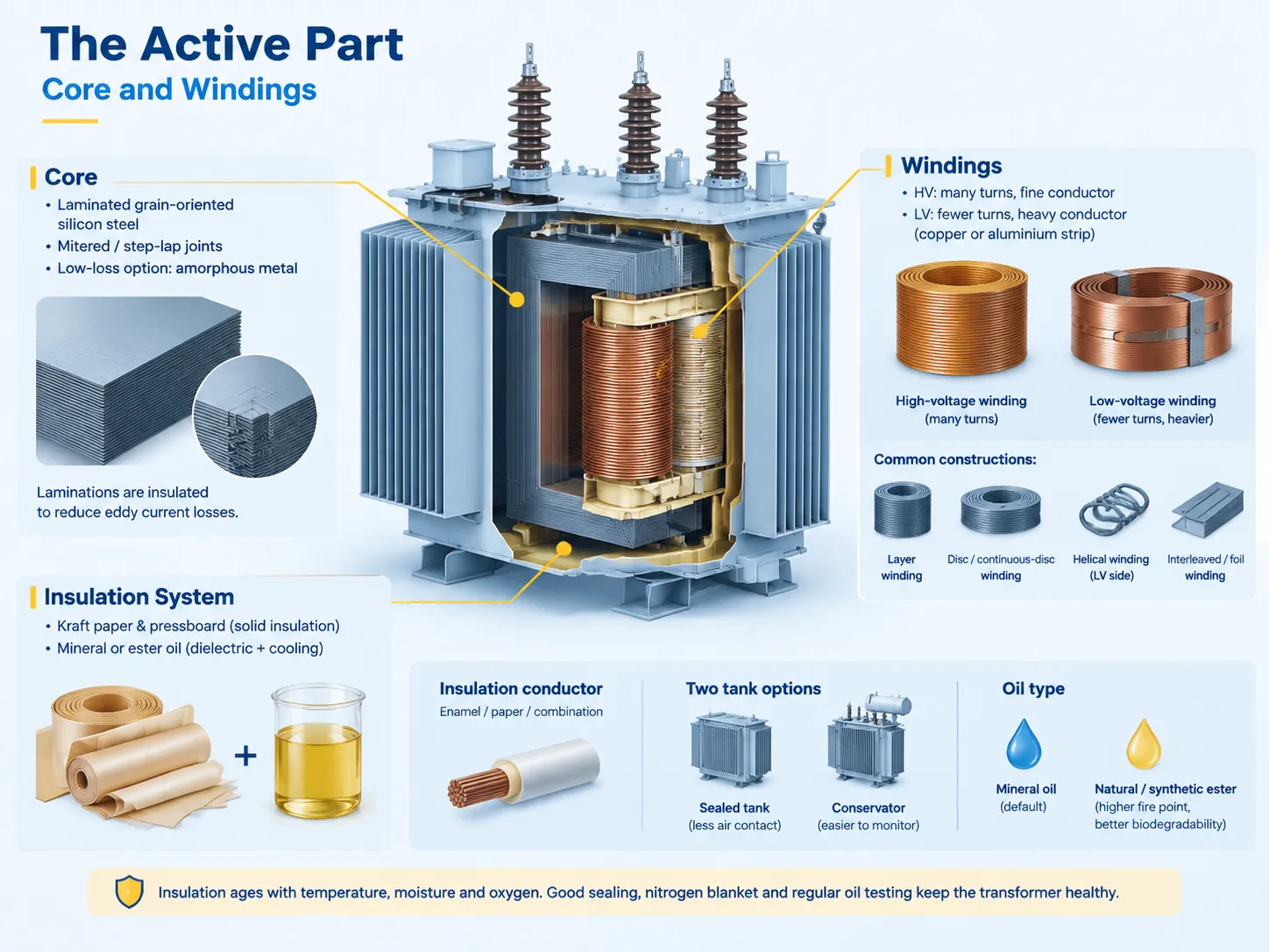
The core consists of the magnetic circuit. It is made of thin sheets of silicon-steel, which are stacked and held together in a frame, and these sheets are insulated from each other by a layer of insulation. Use of lamination is not a matter of convenience in making cores. A core made of solid steel will conduct eddy currents causing heating of the core without any corresponding useful work; for this reason, it has been divided into sheets in order to remove the paths of eddy currents from the core. The latest design of modern cores includes mitered, step-lap joints to minimize the reluctance in the magnetic circuit. The latest innovations refer to low-loss transformers, which use amorphous metals in the core so that the no-load losses become the basic criterion.
The windings are constructed of the electric circuit. In the high-voltage winding, the current is low, and thus the many turns of thin conductor can be used; however, the low-voltage winding must consist of fewer turns and be made of heavy conductor copper, such as aluminum strips. Depending on size and application, various types of windings are used in transformers. For example, layer windings may be used when making small transformers while disc windings can be used in making medium or large-sized transformers.
The core and the windings together form the so-called “active part” of transformers, which is the term used in the industry. When a transformer has been reported to need rewinding, it means that it has to be dismantled inside. The failed winding is replaced and remanufactured to make the assembly usable again. The cost of rewinding varies according to the specifications of each device and not according to the problem.
The Insulation System
Insulation has two functions: in places where there are oil-immersed transformers, both functions are carried out by the same material such as pressboard and Kraft which wraps around the conductors and acts as a barrier between individual windings from each other as well as from the core while ensuring dielectric strength. The insulating oil either mineral or ester provides coverage for insulations that solid ones could not thus provides heat transfer from the winding barrier surface to the body.
The insulating material for conductors is generally enamel or paper or the combination of both. The thermal class determines how far the design goes limiting its capacity; this is why insulation classes are indicated on the rating plate where it accompanies the temperature rise. Aging insulation is affected by moisture temperature as well as oxygen; however; pressure units with nitrogen blankets eliminate this problem by avoiding contact with moisture and oxygen; thus; oil chemistry matters as much as the mechanical condition in such a unit that operates for twenty years.
Two important insulation aspects warrant mentioning regarding the evaluation of the quotations. Firstly, whether it is an insulated unit or one with a conservator equipped with the breather. Sealed installations protect insulations from oxygen contact but sampling is not an easy process. The second factor pertains to the oil type where natural oil has remained the norm but natural and synthetic esters provide better qualities at higher prices.
Tank and Cooling Group
The tank is the enclosure that contains the active part and the oil as well as being the heat exchanger. The tank shape depends on the cooling needs: small distribution transformers use plain or corrugated tanks where the corrugations themselves provide the cooling surface while medium-size transformers utilize radiant devices or tubes, and large units have radiator banks with fans and sometimes oil pumps or separate cooler apparatuses to perform the necessary dissipation.
The cooling system dictates whether the nameplate shows a single or double rating. For example, a unit rated ONAN 1,000 kVA/ONAF 1,250 kVA has both ratings but one of them is usable only during fan operation, hence a failure in the fan results in a reduction in the safe load but there is no increase in the temperature of the unit. In very large units, the cooling stages have a protective interlock that prevents the equipment from being destroyed.
The design of the tank must account for mechanical forces as the core and the windings can generate large forces in a short circuit whereby adequate structural support and containment must be provided. The tank also provides the necessary corrosion protection and therefore determines the allowable installation conditions for outdoor equipment.
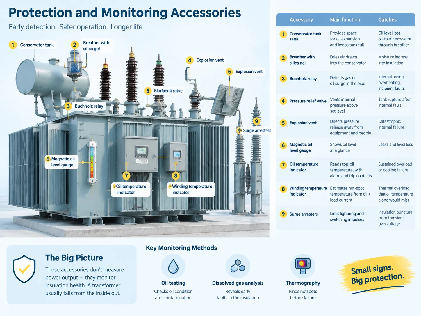
Protection and Monitoring Accessories
The accessory group is where a transformer becomes intricate. This group is responsible for most of the maintenance and alarm tasks. Every device in this group has been designed to indicate a particular failure principle on time.
| Accessory | Function | Failure mode it catches |
|---|---|---|
| Conservator tank | Provides space for oil expansion and keeps the main tank full | Oil level loss, and oil-to-air exposure through the breather |
| Breather with silica gel | Dries air drawn into the conservator | Moisture ingress into the insulation system |
| Buchholz relay | Sits in the pipe between tank and conservator and detects gas or oil surge | Internal arcing, overheating, incipient faults |
| Pressure relief valve | Vents internal pressure above a set level | Tank rupture after an internal fault |
| Explosion vent | Directs a pressure release away from equipment and people | Catastrophic internal failure |
| Magnetic oil level gauge | Shows oil level at a glance | Leaks and level loss |
| Oil temperature indicator | Reads top-oil temperature, with alarm and trip contacts | Sustained overload or cooling failure |
| Winding temperature indicator | Estimates hot-spot winding temperature from oil temperature plus load current | Thermal overload that oil temperature alone would miss |
| Surge arresters | Limit incoming lightning and switching impulses | Insulation puncture from transient overvoltage |
The important thing to observe is that all device become the source of information as to the condition of insulation rather than of the operating condition. Generally speaking, every transformer fails from the inside, its oil temperature, pressure and gas create the very first measurement signs of failure. This is the reason why oil testing, DGA and thermography make part of the serious maintenance programme: they receive accessory evidence that points to failure.
Bushings, Tap Changer and Terminals
The bushings allow for the passage of conductors through the tank wall while providing electrical insulation. The smaller units of this type utilize either porcelain or epoxy resin bushings, but larger units will utilize either oil-filled bushings or condenser bushings if there are any voltage limitations. Bushings fulfill the dual purpose of acting as a pressure barrier as well as electrical insulation, which means that any crack in the bushing will represent both an electric insulation problem and a possible oil leak.
The tap changer serves to modify the turns ratio of the transformer for fixing any variation in supply voltage. The sector of off-circuit tap changers, also referred to as no-load tap changers, is relevant only to distribution transformers as these are used when the distribution transformer is offline or de-energized. The off-circuit tap changer provides the necessary variation of up to + or – 5 percent in intervals of 2.5 percent. The on-circuit tap changer is used on purpose transformers when it is necessary to keep the voltage constant at all times as it enables tap switching when the transformer is under load by utilizing a transition resistor or reactor. The on-load tap changer is the part that experiences maximum maintenance in the transformer.
The last stage of the assembly comprises of the terminals and connections which will include both the primary and secondary terminals, the neutral terminals on the low voltage side when star connection is used, the earthing terminals that have to be interconnected with the earthing facility and the cable boxes or busbar chambers which will allow for the easy connection of the conductors with the transformer.
Full Parts List at a Glance
| Group | Part | What it does |
|---|---|---|
| Active part | Core | Carries the magnetic flux; laminated to limit eddy currents |
| Active part | Windings | Carry current; turn counts set the voltage ratio |
| Active part | Core clamp and frame | Holds the lamination stack rigid under fault forces |
| Insulation | Kraft paper and pressboard | Dielectric barrier between conductors and to earth |
| Insulation | Insulating oil or resin | Additional dielectric strength and heat transfer |
| Insulation | Oil ducts and spacers | Create oil circulation paths inside the winding |
| Tank and cooling | Tank or enclosure | Contains oil and active part; primary heat exchanger |
| Tank and cooling | Radiators, tubes, corrugations | Increase the heat-dissipating surface |
| Tank and cooling | Fans and oil pumps | Raise the achievable rating above the natural circulation figure |
| Tank and cooling | Base, skid or rollers | Supports the unit and allows positioning |
| Accessories | Conservator, breather, Buchholz relay | Oil management and internal fault detection |
| Accessories | PRV, explosion vent | Pressure relief after an internal fault |
| Accessories | OTI, WTI, oil level gauge | Thermal and level monitoring with alarm contacts |
| Accessories | Nameplate and marshalling box | Ratings record and the interface for control and protection wiring |
| Connections | Bushings | Insulated conductor entry through the tank |
| Connections | Tap changer | Adjusts the turns ratio for supply variation |
| Connections | Terminals and earthing points | Electrical connection and protective earthing |
How the Parts Differ in a Dry-Type Unit
The dry-type transformer is similar to an oil transformer in that it retains the core, windings, and bracing, but the oil system is entirely removed. The windings are either vacuum-cast in epoxy or impregnated and varnished, while the cooling is through ducts that allow forced or natural air to flow through the core and enclosure. This means that the oil tank, conservator, breather, Buchholz relay, radiators, etc., are all removed along with any oil-related failure modes.
The oil system is replaced by this thermal design, which uses an air-based system. Instead of oil, dry-type transformers now have winding-temperature sensors in the winding, thermal relays, and cooling fans with their own control circuit. The advantages of this switch are simple. First, it is impossible for a dry type to leak oil. Second, it will perform better in the event of a fire. Third, it will be appropriate for use in occupied indoor buildings. However, dry types are typically larger than oil types and more costly for the same rating. Additionally, they are more sensitive to ambient temperature and dirt. And last, the dry-type transformers cannot be upgraded through installation of radiators later.
This choice also alters the requirements for the structure. An outdoor oil-filled unit is often quoted as a complete package, which is why many of the projects utilizing oil-filled transformers employ prefabricated substations rather than separate transformer and switchgear buildings.
RUY Power builds those projects around the YB□-12/0.4 prefabricated substation in the European format, which houses high-voltage switchgear, transformer and low-voltage switchgear in one enclosure from 50 to 1,600 kVA.
Where the transformer, fuse protection and metering have to sit in a single weatherproof unit instead, the ZGS13-H-630/10 combined transformer covers the American box-type format, with the transformer and its protection scheme sharing one enclosure rather than occupying a switchroom.
The production and testing stages that apply to both formats are described on our manufacturing page.
Which Parts Fail First
The statistics from the failure reports across the electrical sector lists the various types of failures in transformers that occur, and does not include winding insulation. Winding insulation is characterized by the earliest failure, which usually happens as a result of prolonged thermal aging or overload, and the failure happens within the transformer that is detectable through Buchholz relays or differential protection. Subsequently, problems are encountered in bushings whereby mechanical damage, contamination of the bushings, or the ingress of moisture are likely to take place. Tap changers are responsible for a disproportionate rate of failures occurring in large transformers due to their moving parts and the presence of oil compartment. For the purposes of accessories failure rates include all those movable parts such as fan, gauge and breather which fails cheaply.
The aforementioned ranking results in some effect on purchasing practice, which implies that the ordering factor for transformer components must be the winding insulation, oil and tank seal. It must be the results of ordering specification pressure and process control of the supplier.
FAQ
What are the main parts of a transformer?
The basic components of a transformer include the following: core, primary and secondary windings, insulation made of paper and oil or resin, enclosure or tank, cooling apparatus and accessories including bushings, tap changer, conservator, breathers, Buchholz relay, pressure relief valve and temperature indicators. The core and windings form the active part of a transformer.
What are transformer body parts called?
The external body or tank of the transformer (for packaged units, the enclosure) is called the tank. Within the unit there is an internal assembly called the active part which comprises the core and windings. Other important components include the bushings located at the top and terminals located in the cable box which connect the transformer to the system and the conservators and breathers, Buchholz relay, pressure relief valve, oil level gauge and the temperature indicators which protect it.
Which transformer component fails most often?
The most common failures as per the service records state winding insulation due to thermal effects while the part of the transformer which needs more attention is the accessories i.e. cooling fan, breathers, gauges and on load tap changers and so on for the large transformers. Bushing failure is also fairly common where the cause is mostly due to external damage.
How do you tell an oil-immersed transformer from a dry-type one?
One can easily identify oil immersed transformers by looking at the oil system comprising the tank, radiators or corrugated walls, conservator with breathers and Buchholz relay, along with bushings on the top. Dry type transformers are devoid of any oil gauges or pressure systems while they have air vented or louvered enclosure, cast resin or varnished windings and ducts for cooling.
What is the difference between the core and the winding?
The core is the magnetic part of the transformer while the windings form the electrical circuit. The core is magnetic and made of laminated silicon steel while the winding is made of copper and aluminum conductors which are insulated.
References
- International Electrotechnical Commission — IEC 60076 series, Power transformers, including fittings and accessories requirements
- IEEE Standards Association — IEEE C57.12.00 and C57.12.90, transformer general requirements and test code
- International Electrotechnical Commission — IEC 60296, Fluids for electrotechnical applications: mineral insulating oils
- NFPA — NFPA 70B, Recommended Practice for Electrical Equipment Maintenance
- US Department of Energy — Transformer and grid equipment reliability resources
Conclusion
The components of a transformer can be classified into four groups based on their functions. These include the active part that transforms energy, the insulation system which acts as a separator and cooler, the tank-cooling group that helps remove heat, and the accessory group which provides monitoring and protection services. Once components are categorized properly in this way, it counteracts ambiguity in reading a datasheet or making a price comparison since each line will either pertain to energy transformation, heat removal, or protection.
Keep these three practical things in mind: first, check the active part construction if you want to evaluate quality since core steel and winding type will determine efficiency and short-circuit capacity; second, request the accessory list along with manufacturer names if you want to check off-serviceability because this is where the most failure occurs and the most reorders will come from; finally, recognize the leakage and insulation system, which represent the limited sustainability of performance since it will determine whether the unit will last twenty-five years or require rewinding in twelve.
Labeling parts accurately allows for providing feedback accurately, leading to shorter conversations regarding repairs.