
A capacitor bank sizing calculator should answer more than “how many kVAR”. Before you order an automatic bank, you also need to know how the kVAR splits into steps, whether the bank over-corrects at night, and whether any step level resonates with your transformer. The calculator below does all four for three-phase systems at 50 Hz or 60 Hz. The text after it explains each result. For the full selection process — tariffs, measurement, fixed vs automatic, standards — see our guide on how to size and select a power factor correction capacitor bank.
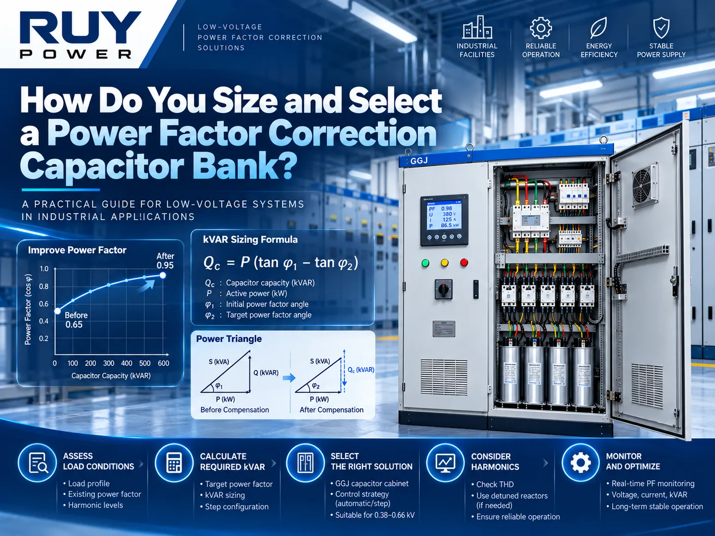
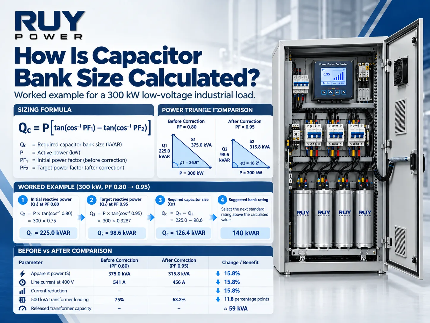
How do you calculate capacitor bank size? Use Qc = P × [tan(arccos PF1) − tan(arccos PF2)], where P is the real power in kW at peak demand, PF1 is the existing power factor and PF2 is the target. A 300 kW load corrected from 0.80 to 0.95 needs 126.4 kVAR. Add a margin of about 5% and round up to a step arrangement, for example 10 + 7 × 20 = 150 kVAR in eight steps. Then check two things: that the smallest step suits the light-load demand, and that no step level resonates near the 5th, 7th, 11th or 13th harmonic.
Capacitor Bank Sizing Calculator
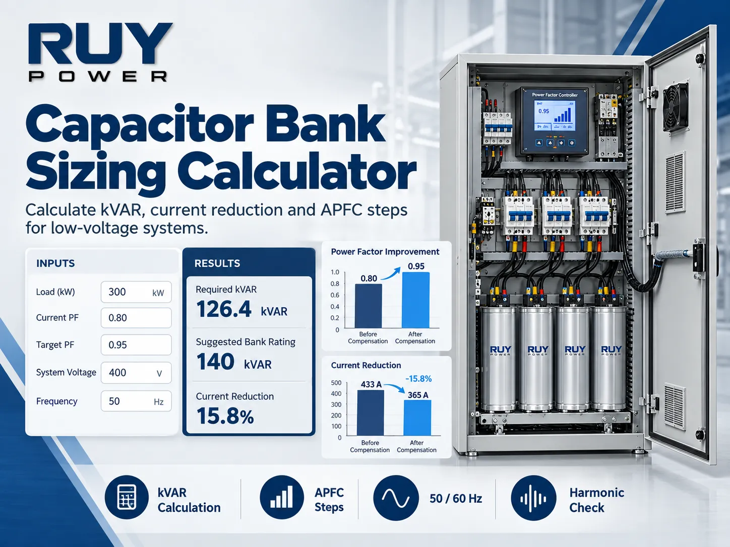
Three-phase, 50 Hz or 60 Hz. Gives the kVAR, an automatic step arrangement, currents, a light-load check and a resonance check. Results are preliminary and should be confirmed with measured data.
1 · Load at peak demand
2 · System
3 · Light load and bank design
Before and after correction
| Quantity | Before | After |
|---|---|---|
| Power factor | – | – |
| Reactive power from supply (kVAR) | – | – |
| Apparent power (kVA) | – | – |
| Line current (A) | – | – |
| Transformer loading | – | – |
Automatic step arrangement
Bank ratings
| Rated current of the installed bank | – |
| Minimum conductor and protection rating (1.35 × rated current) | – |
| Suggested minimum capacitor rated voltage | – |
| Capacitance per phase, delta connection, whole bank | – |
Light-load check
Harmonic resonance check
Equipment fit
Using the Capacitor Bank Sizing Calculator
Different inputs lead to different results, so using accurate values rather than estimates is recommended.
Peak real power (kW). Use the highest 15-minute peak load from a week’s readings, or from your utility bill. Avoid using a transformer plate.
Power of the existing load. Provide your kW number if available or switch the calculator to kVA or kVAR mode, depending on what your bill shows. The calculator converts accordingly.
Desired power factor. 0.95 is a common value. Having a power factor above 0.98 gives you very little benefit.
Voltage and frequency. This will influence kVAR and current calculations. A 60 Hz power system requires a bank that is rated for that frequency.
Transformer rating and impedance. Both should be found on a transformer plate. The calculator will make use of this data to complete transformer loading and resonance calculations.
Minimum load and its power factor. These values are relevant during night shift and weekends. They serve to determine the light-load calculations.
Controller outputs and detuned reactor. This allows for calculating the number of steps and whether the bank is standard or reactor protected.
With this information, the calculator acts as a 3 phase capacitor bank calculator. If you only need kVAR, it is also a quick kVAR calculator. It functions as an APFC panel sizing calculator. The only difference for a single-phase load is in current calculations: I = kVA x 1,000 / V.
Capacitor Bank Sizing Calculation: A 480 V, 60 Hz Example
The calculator unveiled with an ordinary light industrial casing. The power station has maximum power demand of 300 kW at PF 0.80 and, thus, a 1,000 kVA, 5.75% transformer operates at 480V, 60 Hz. While at night the load demand is 90 kW at PF 0.72. The target for power factor is PF 0.95.
| Result | Value | How it is derived |
|---|---|---|
| Required kVAR at peak | 126.4 kVAR | 300 × (0.750 − 0.329) |
| Suggested bank | 150 kVAR | 126.4 + 5% = 132.7, rounded up to 10 + 7 × 20 kVAR |
| Line current | 451 A → 380 A | kVA × 1,000 ÷ (√3 × 480), a 15.8% reduction |
| Upstream I²R losses | −29.1% | 1 − (315.8 ÷ 375.0)² |
| Bank rated current | 180 A | 150,000 ÷ (√3 × 480); cables and protection ≥ 244 A |
| Light load, automatic bank | 60 kVAR in service → PF 0.96 lagging | 90 kW needs 57.2 kVAR |
| Light load, if fixed | PF 0.82 leading | 150 kVAR against 86.7 kVAR of load reactive power |
| Resonance | 13th to 11th harmonic between 90 and 150 kVAR | h = √(17,391 ÷ kVAR in service) |
Two of the above results change your purchase options. The light load tests imply that a 150 kVAR capacity bank must be automatic since it will bring the plant up to yet another PF of 0.82 on a regular basis at night. The resonance tests show that the upper four steps are at the 11th and 13th harmonic levels. If the plant has high variable drives, it is necessary to opt for a detuned bank.
How to Read the Results
Step Arrangement
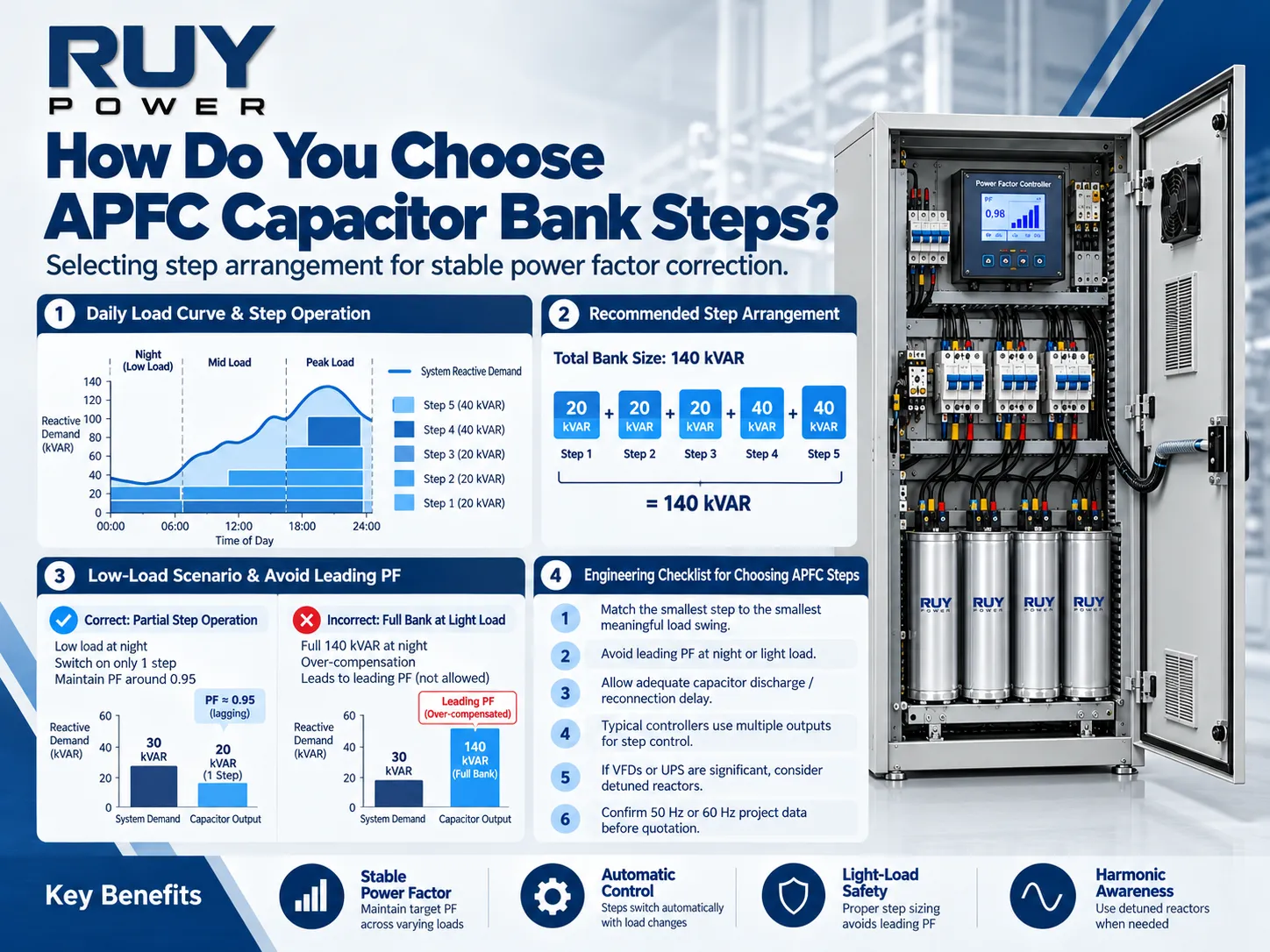
The capacitor bank steps are calculated using the ratio of one to two to two, where the first step is only half the amount compared to the other steps and hence a controller operated in this ratio can accurately attain all multiples of the smallest step. With an output of 8 and a 10 kVAR first step, one achieves 10 kVAR accuracy ranging from 10 to 150 kVAR. More controller outputs give higher accuracy from the viewpoint of contactors and fuses as well. The GGJ series of cabinets offered by RUY can operate with as many as 16 controller circuits.
Light-Load Check
Where this arrangement of big or established bank does not do well is if the first step exceeds the kVAR required by the light load, making the controller unable to achieve the desired value. It then makes the plant either lagging or forcing it to be leading. Leading power factor increases the voltage and may attract tariffs. The solution would be smaller first step or higher number of controller outputs.
Harmonic Resonance Check
Each switch step lowers the frequency of the resonant combination of transformer & capacitor. The table indicates the resonances of various levels of kVAR in operation and indicates harmonic levels close to the 5th, 7th, 11th & 13th harmonics. The calculations do not consider the upstream network reactance, so the actual resonances would be lower than computed values. If the total rating of drives, UPSs and rectifiers is more than about 25% of the transformer rating, it is necessary to use a 7% detuned reactor. The frequency of tuning will then be indicated by the calculator as 189 Hz for 50 Hz networks and 227 Hz for 60 Hz networks.
Bank Ratings
The primary switch, cables, and busbars are defined by given current. Factor of 1.35 × is suitable according to NEC 460.8 standard regarding the capacity of conductors. Similar IEC standard uses factors 1.3–1.5 ×. The recommended capacitor voltage is above the system voltage and even more with a reactor. A 7% reactor at 400 V would give 430 V to the capacitor. The capacitance per phase allows verifying the calculations with the capacitor specification.
What the Calculator Does Not Replace
Similar to any power factor correction tool, it operates through displacement power factor and fundamental frequency in your setup and cannot track your loading conditions impacted by harmonic distortion or frequent changes of the load or by the utility pricing policy, which accounts for leading power factor-based consumption. Use it to calculate the amount of capacitive reactance required and to select the type of capacitors. Then carry out further analysis of one-week power quality, especially focusing on THD readings and 5th and 7th harmonics.
From Calculation to Quotation
The results map directly onto an RUY GGJ low-voltage capacitor compensation cabinet. GGJ is manufactured for 0.38–0.66 kV at 50 Hz or 60 Hz and has 1–600 kVAR per cabinet, and 1–16 control circuits. Detuned reactors are also available. For greater requirements, the solution will consist of several cabinets. To make the request, use “Email results for a quotation” field in the calculator. The email processor will create pre-populated email with the results and information about a project country and harmonics information.
Frequently Asked Questions
How do you calculate the size of a capacitor bank?
Multiply the real power in kW by tan(arccos PF1) − tan(arccos PF2). At 300 kW, going from 0.80 to 0.95, that is 300 × 0.421 = 126.4 kVAR. Add about 5% margin, then round up to a practical step arrangement.
How do I convert kVA and power factor to kVAR?
kVAR = √(kVA² − kW²), or kW × tan(arccos PF). A load of 375 kVA and 300 kW draws 225 kVAR. In the calculator, choose “Apparent power (kVA)” and it does the conversion for you.
How many steps should an automatic capacitor bank have?
Enough that the smallest step is below the light-load kVAR demand. For most plants that means 6–12 steps. A 1:2:2 ratio gives the finest resolution for a given number of controller outputs.
How do I convert kVAR to microfarads?
For a three-phase delta bank, the capacitance per phase is C (µF) = kVAR × 10⁹ ÷ (3 × 2π × f × V²), with V the line-to-line voltage. For example, 150 kVAR at 480 V, 60 Hz gives about 576 µF per phase.
Can I use the same capacitor bank size at 50 Hz and 60 Hz?
Not the same hardware. A capacitor delivers 20% more kVAR at 60 Hz than at 50 Hz. Detuned reactors are tuned for one frequency only. Size the bank in kVAR at your system frequency, and order it rated for that frequency.
References
- IEC 61921 — Power capacitors: Low-voltage power factor correction banks. Requirements for complete LV PFC banks.
- IEC 60831-1 — Shunt power capacitors of the self-healing type, up to 1,000 V. Capacitor ratings and overload limits.
- NFPA 70 — National Electrical Code, Article 460. Conductor sizing (460.8) and discharge of stored energy (460.6).
- Eaton — Power Factor Correction and Harmonic Resonance: A Volatile Mix. The resonance estimate used in the calculator.
- Schneider Electric — Electrical Installation Guide. Gh/Sn rule for standard, heavy-duty and detuned banks.
- RUY Power — How Do You Size and Select a Power Factor Correction Capacitor Bank? The full selection guide.
Need a Capacitor Bank Sized for Your Plant?
A capacitor bank sizing calculation takes a few minutes. Turning it into a bank that holds the target power factor day and night takes measured load data and a check of the harmonics. Send RUY Power your calculator results, together with system voltage and frequency, transformer data, harmonic measurements and the project country. Our engineers will confirm the step arrangement and a GGJ configuration for 50 Hz or 60 Hz. Contact RUY Power for a quotation.