
When one opens the front door of the low-voltage distribution cabinet, a sight of two sorts of conductors can be seen. Strong copper busbars convey services of hundreds of or more amperes from the at the supply entrance to the circuits. At the back of the instrument door there is a multitude of fine wires linked to measuring tools, indicator devices and relays. Both the elements are part of electrical cabinet wiring, with the major proportion of commissioning issues occurring at these points.
In this article, LV switchboards or cabinets will be considered in terms of the wiring scheme including the difference between the power circuit and auxiliary circuits, the wiring standards in electrical cabinets (IEC 61439, IEC 60204-1 and UL 508A), how to read the electrical cabinet wiring diagram, the rules of color and marking, as well as the procedures that allow for the drill mistakes in course of the work. The examples will be provided from the engineering materials of Siemens, ABB, Schneider Electric, Rittal and Phoenix Contact, as well as RUY Power’s cabinets including GGD, GCS, MNS and XL-21. The focus will be on the power distribution equipment construction and not on PLC and machine controls.
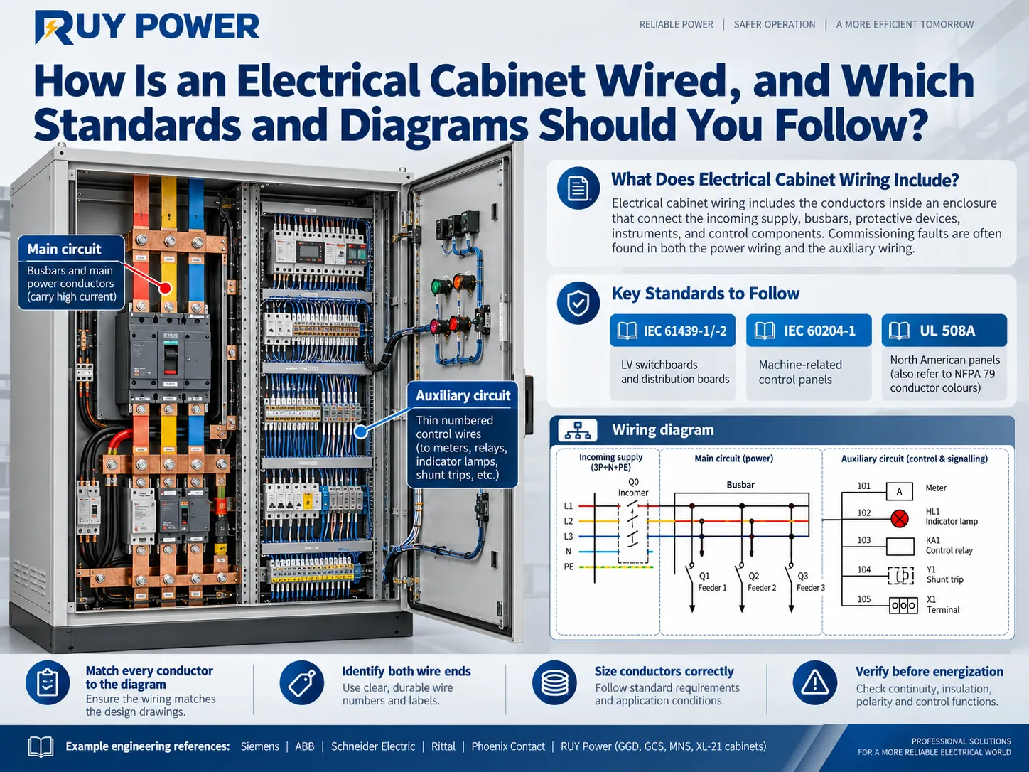
Quick answer: Electrical cabinet wiring refers to the collection of wiring present within an electrical cabinet designed to connect the incoming supply of electricity, busbars, protective devices, measuring instruments, and control elements to each other and form functionality circuits. In a low voltage switchboard, there are two circuits: the primary circuit consists of busbars and power cables, while the secondary circuit comprises control, measuring, and signaling wires. Switchboards and distribution boards are manufactured according to standard IEC 61439-1/-2; control panels included in the machine are made according to IEC 60204-1; panels intended for the market of North America are made mostly according to standard UL 508A which uses NFPA 79 color coding. Regardless of the standard applied, it’s important to point out that the conductors must follow the existing wiring diagram, be identifiable from both sides, be sized according to the amperage and fault level it should withstand, and checked before leaving the factory.
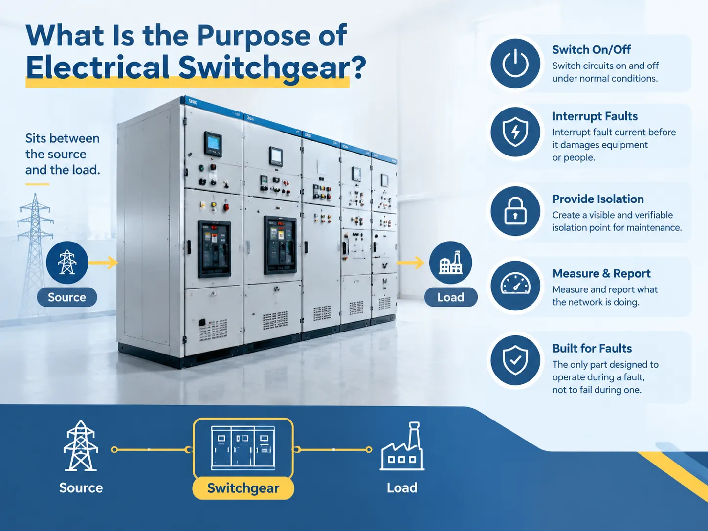
For a general introduction to what switchboards and switchgear do, see our guide to the purpose of electrical switchgear. This article focuses on what happens inside the cabinet.
What Is Electrical Cabinet Wiring?
The term electrical cabinet refers to an assembly that has been factory built and involves power distribution. In simpler terms, an electrical cabinet would involve a box or enclosure that has busbars, devices for switching, instruments, and connecting wires that would help get the cabinet to work properly. Therefore, the process of electrical cabinet wiring also involves the connection of all those components electrically and is done using one proper circuit wiring or main wiring.
About Main Circuit Wiring
The term main circuit refers to the circuit involving electrical loads and determining whether the cabinet is in a fixed type like GGD or is in a withdrawable board that could be GCS or MNS. The main circuit wiring usually includes:
1. Horizontal busbars that are situated along the cabinet with a rating that can range from 630 A to about 5000 A.
2. Vertical busbars that will ensure that power supply gets to the required functional unit through various sections.
3. Copper links or flexible connectors among components.
4. Neutral and protective earth.
5. Outgoing power cables.
Generally speaking, the main circuit wiring involves mostly copper use which is why things like bar size and total areas involved in the operations of the circuit should be taken into consideration.
The Concept of Auxiliary Circuit Wiring
The auxiliary circuits are not associated with the provision of an electrical current and solving other issues associated with it. Much of the information associated with this concept can be transferred through them. They include:
1. The use of CTs, voltmeters, and other components that are associated with working with currents and voltages.
2. Breaker operating elements and motors.
3. The auxiliary switches and communication links.
Why Distinctions Between Switchboard and Control Panel Matter
While both switchboard and control panel have steel enclosures which makes the process of wiring seem straightforward, IEC has its standards for switchboards including specifics for different kinds of switchboards. Control panels that use electricity in the assembly would refer to IEC standards because it covers all things related to the electrical and chemical processes taking place there.
Which Electrical Cabinet Wiring Standards Apply?
Three documents cover most electrical cabinet wiring standards questions buyers and contractors ask. They overlap, but they are not interchangeable.
| Standard | What it covers | Typical cabinets | What it says about wiring |
|---|---|---|---|
| IEC 61439-1 / IEC 61439-2 | Low-voltage switchgear and controlgear assemblies up to 1000 V AC / 1500 V DC | Main LV switchboards, distribution cabinets, MCCs, capacitor compensation cabinets | Requirements for internal electrical circuits and connections (main circuits, auxiliary circuits, bare and insulated conductors, protection of unprotected live conductors against short circuits); design verification of temperature rise and short-circuit withstand; routine verification of wiring against the drawings |
| IEC 60204-1 | Electrical equipment of machines, from the machine supply point onward | Machine control panels, process skid panels | Conductor identification and recommended colours, wire sizing tables, technical documentation (circuit diagrams, interconnection diagrams) |
| UL 508A (with NFPA 79) | Industrial control panels for the US market | Control panels, some distribution panels for North American projects | Construction, spacing, short-circuit current rating (SCCR) and grounding; NFPA 79 sets the conductor colour convention for industrial machinery |
Two important remarks. First of all, the IEC 61439 standard supersedes the previous IEC 60439 denomination, yet many datasheets from China continue to reference the previous GB 7251 or IEC 60439 codes. Thus, check the requirements of your specifications. Second, the core of the IEC 61439 standard is the distribution of responsibilities among the parties. Although the manufacturers are responsible for the devices that they make, final responsibility for internal wiring and conducting external elements is on the manufacturer of the assembling equipment.
Electrical Cabinet Wiring Standards: Siemens IEC Design Practices
Siemens is publishing a reference book and offering free tools for the construction of IEC control cabinets, making its approach a good example for any panelmaker.
Begin with scope by determining the applicability of IEC 60204-1, IEC 61439-1, and IEC 61439-2 and completing the risk assessment.
Acquire the short-circuit parameters from the supply to the cabinet and from the cabinet onward. Siemens has its SIMARIS program to accomplish this and the TIA Selection Tool for making electrical calculations and technical documentation.
Consider temperature rise as part of the design rather than an afterthought. In their IEC 61439 compliance guide, Siemens stresses the importance of temperature-rise verification and explains that a 5 °C lower cabinet temperature prolongs the component life by at least 20%; while taking into account that thermal losses occur as a result of the complication of the design, temperature rise must be among the design considerations.
Plan your design considering EMC. Make sure power and signal conductors are installed separately and that enclosures and cable shields are properly grounded.
ABB’s Technical Application Paper No. 11 providing guidelines for the design of LV equipment in accordance with IEC 61439-1 and -2 covers the same principles from the switchboard point of view.
Wire Colours and Conductor Marking
Colour tells an electrician what kind of circuit a conductor belongs to; the wire number tells them exactly which one. Good control panel wiring uses both.
| Function | IEC 60445 / IEC 60204-1 practice | NFPA 79 (used with UL 508A) | Chinese GB practice (common in GGD/GCS/MNS) |
|---|---|---|---|
| Phase busbars / phase conductors L1, L2, L3 | Brown, black, grey | Black for ungrounded power conductors (phase identified by markers) | Yellow, green, red |
| Neutral N | Light blue | White or grey | Light blue |
| Protective earth PE | Green-and-yellow (reserved for PE only) | Green or green-and-yellow | Green-and-yellow |
| AC and DC power circuits inside the panel | Black (recommended) | Black | Often black or phase colours |
| AC control circuits | Red (recommended) | Red | Project-specific; often red or black |
| DC control circuits | Blue (recommended) | Blue | Project-specific; often blue or brown |
| Interlock circuits fed from an external source | Orange | Orange | Should be specified in the order |
IEC 60204-1 provides a list of recommended colours, while it states that green and yellow are to be used for protective conductors and light blue is set for neutral conductors. As different markets have different conventions, it is important to agree on chosen colour scheme with the purchase order and present a colour legend on the first sheet of the drawings.
Marking is as serious as colour. There must be ferrule or printed sleeve with an identification number at both ends of the conductor that must be the same as in the drawings, either terminal identification number (-X1:5) or wire number. According to North American regulation NFPA 79 every conductor has to be marked at each point of termination. Rittal provides for printing on wire with the help of its wire processing machines in black, white or light blue even before the wire reaches the cabinet.
How to Read an Electrical Cabinet Wiring Diagram
“Wiring diagram” is used loosely. For a switchboard order, the drawing package usually contains several documents, each answering a different question.
The drawing set for an LV cabinet
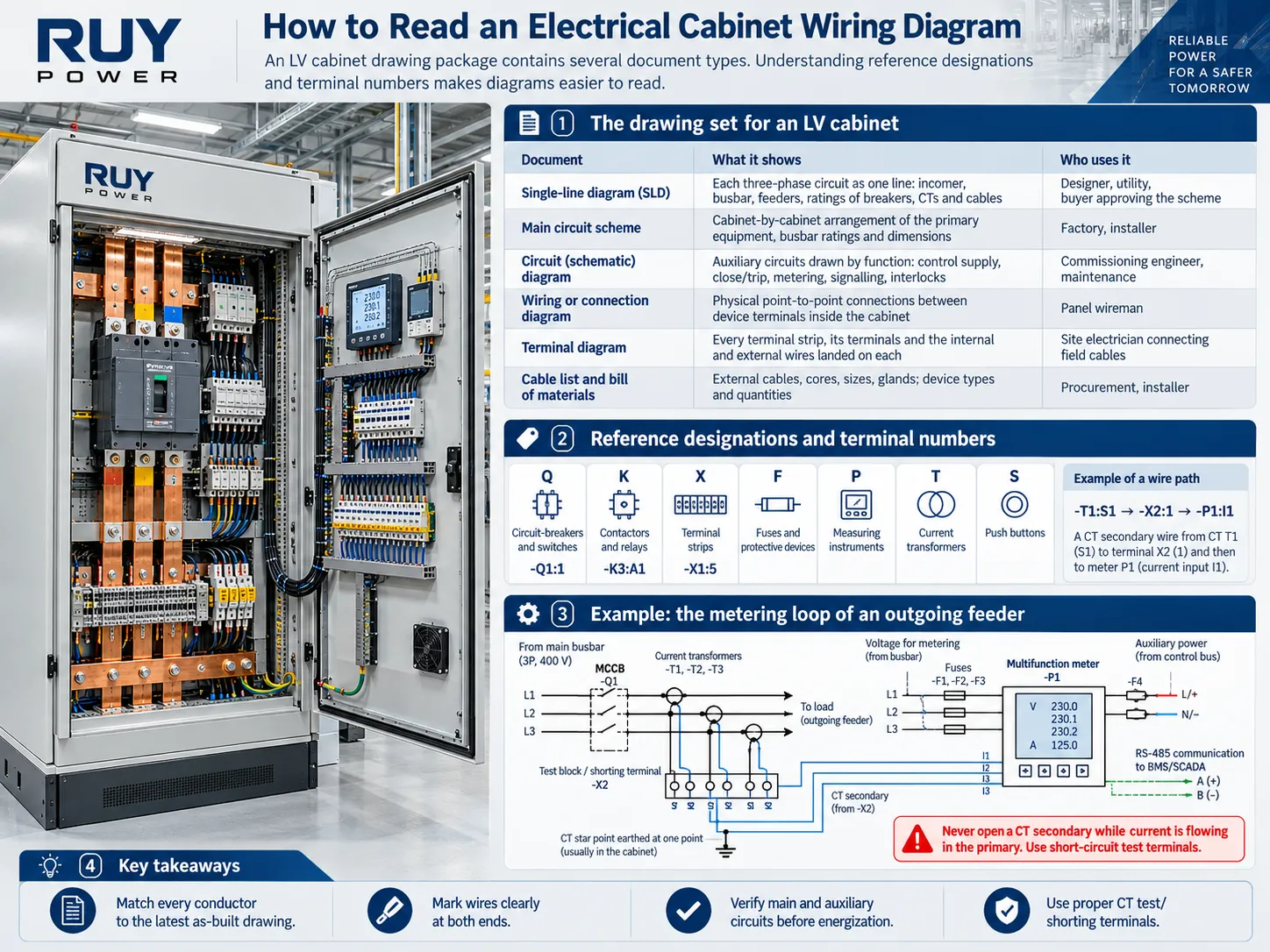
| Document | What it shows | Who uses it |
|---|---|---|
| Single-line diagram (SLD) | Each three-phase circuit as one line: incomer, busbar, feeders, ratings of breakers, CTs and cables | Designer, utility, buyer approving the scheme |
| Main circuit scheme | Cabinet-by-cabinet arrangement of the primary equipment, busbar ratings and dimensions | Factory, installer |
| Circuit (schematic) diagram | Auxiliary circuits drawn by function: control supply, close/trip, metering, signalling, interlocks | Commissioning engineer, maintenance |
| Wiring or connection diagram | Physical point-to-point connections between device terminals inside the cabinet | Panel wireman |
| Terminal diagram | Every terminal strip, its terminals and the internal and external wires landed on each | Site electrician connecting field cables |
| Cable list and bill of materials | External cables, cores, sizes, glands; device types and quantities | Procurement, installer |
The IEC 60204-1 specification provided by Siemens and the regular checking process in IEC 61439 contain the assumption of the presence of this documentation and its conformity to the actual cabinet. Practically speaking, not having an updated electrical cabinet wiring diagram which reflects “as-built” status is among the most frequent reasons for delays during site acceptance.
Reference designations and terminal numbers
The majority of drawings from Europe and many Chinese drawings use IEC 81346 codes to indicate equipment. As soon as one learns these codes, the reading of diagrams becomes relatively simple.
*Q: for circuit-breakers and switches, for example -Q1:1 refers to terminal 1 of the circuit-breaker Q1.
*K: for contactors and relays, for example -K3:A1 refers to coil terminal A1 of the contactor K3.
*X: indicates terminal strips, for example -X1:5 indicates terminal 5 of the terminal strip X1.
*F: indicates fuses and protective devices; *P: indicates measuring instruments; *T: indicates current transformers; *S: indicates push buttons.
Next, wires in the connection diagram run from one code to the other, for example -T1:S1 to -X2:1 to -P1:I1. Such drawings are created by EPLAN software, and the data from them can be used by Rittal Wire Terminal machines to produce wires according to this diagram.
Example: the metering loop of an outgoing feeder
An ordinary outgoing circuit in either a GGD or GCS cabinet equates to three current transformers (CTs) on the load side of the MCCB, ammeter or multifunction meter mounted on the door, and a voltage tap powered from the bus via small fuses. This chart shows:
1) The CT secondary circuits connected to either a test block or shorting terminal blocks before passing through meter inputs, using star points grounded only at one location;
2) The voltage circuits accessed from the bus by means of -F fuses before they pass through the meter terminals;
3) The auxiliary power supplied to the meter from the control bus, and an RS-485 pair connected to the communication terminals if the board is monitored.
The most important requirement to remember is never to open a CT secondary when there is a flow of current through its primary coil. This means that it is mandatory to use short-circuit testing equipment designed especially for this purpose. For instance, the XTVMEA 6 measurement transducer terminal blocks from Phoenix Contact automatically enable the short circuit before the switch opens.
The Process of Wiring a Low Voltage Switchboard
While every factory has their own wiring processes for switchboards, there is a common procedure that can be followed.
1.Installation of the busbars and main connection. The copper bars are cut, drilled, tinned in required places and are bolted down to the insulators. Each connection is tightened according to required torque specifications. According to the Prisma assembly handbook by Schneider Electric, every tightened nut must be marked with an indelible lacquer that can withstand high temperatures to ensure successful torque check later on.
2.Establishing of the protection circuit. Bonding the frame, mounting plates and PE busbar must be carried out. Door mounting equipment requires flexible copper bonding conductor and not only hinges.
3.Device installation and labeling. After the breakers, relays and contactors are mounted and fixed in position, a labeling procedure is undertaken still before wires are fitted.
4.Routing of the auxiliary wiring. While installing auxiliary cables, correct route should be chosen in order to protect these cables and also separate them from each other.
5.Proper wiring termination. When using flexible stranded cable it is advisable to use ferrules. Be careful to use only one conductor per clamp unless the terminal can take two conductors and use correct torque at the screw terminals. The Push-in terminals save wiring time as stated by Phoenix contact corporation.
6.Marking of the wires. Proper markings must be made to all wires at their ends using ferrules or sleeves with terminal diagram designations.
7.Documentation keeping. It is necessary to keep wiring plan at the door of the switchboard.
8.Daily checks. Tests must be conducted for checking the protection circuit, dielectric tests and verifying wiring against the drawings as described in the IEC 61439 standard.
The major drawback of the wiring process is that it is very labor oriented. Rittal reports that in the switchboard production the wiring process takes almost 50% of the total processing time in the production process, that is why automatically produced wirings, pre-branded wires and Push-in terminals are becoming more and more popular in the market.
What Wire Size Is Used for Cabinet Control Wiring?
Main circuit conductors are sized from the load current, the short-circuit rating and the temperature rise of the assembly. Auxiliary circuits follow simpler rules of thumb, which project specifications usually confirm:
| Auxiliary circuit | Common minimum (copper) | Notes |
|---|---|---|
| CT secondary (current) circuits | 2.5 mm² | GB 50171 practice for Chinese switchgear; larger if the CT is far from the meter or relay and the burden is tight |
| Voltage measuring and control circuits | 1.5 mm² | Fused at the tap; insulation rated for the circuit voltage |
| Electronic and low-power signal circuits | 0.5 mm² and above | Only where current, voltage drop and mechanical strength allow; shielded twisted pair for RS-485 |
| Motor-operator and spring-charging supplies | Per device rating, typically 1.5–2.5 mm² | Check the motor’s starting current and the protective device |
IEC 60204-1 and UL 508A have their own sizing tables, so for a machine panel or a US project use those instead of the figures above.
Common Electrical Cabinet Wiring Mistakes and How to Catch Them
| Mistake | What goes wrong | How to prevent or detect it |
|---|---|---|
| CT secondary open-circuited, or no shorting terminal | Dangerous voltage across the open terminals, CT damage | Shorting or test terminal blocks; continuity check of every CT loop |
| Busbar joint not torqued | Hot spot, discoloration, eventual failure under load | Calibrated torque tool, lacquer marking, thermal imaging at commissioning |
| Two conductors forced into one clamp or ferrule | Loose connection, intermittent faults | Twin ferrules or double-level terminals; pull test during inspection |
| Control wires bundled against busbars or power cables | Insulation damage under fault, interference in measuring and communication circuits | Separate ducts and routes; clearance check before closing covers |
| Door wiring with no flexible loop | Conductor fatigue at the hinge, broken cores | Flexible stranded wire, hinge loop, strain relief at both ends |
| PE not continuous to doors and mounting plates | Exposed metal parts not earthed | Bonding conductors; protective circuit continuity test |
| Wire numbers do not match the drawings | Failed factory acceptance test, slow fault finding | Marking at both ends; as-built drawings delivered with the cabinet |
| Phase colour convention not agreed (GB vs IEC) | Confusion and errors during site connection | State the busbar and wire colour scheme in the purchase order |
For checks that continue after installation, see our article on switchgear maintenance and testing.
How Major Brands Approach Cabinet Wiring
Looking at how leading manufacturers support panel builders shows where the industry is heading.
| Brand | Products and tools relevant to cabinet wiring | What it means for the buyer |
|---|---|---|
| Siemens | IEC reference manual for control panels; SIMARIS design and SIMARIS therm; Electrical Designer in the TIA Selection Tool | Short-circuit, temperature-rise and documentation evidence can be generated, not guessed |
| ABB | MNS low-voltage switchgear platform; Technical Application Paper No. 11 on building assemblies to IEC 61439 | A reference for modular withdrawable boards and IEC 61439 verification |
| Schneider Electric | Prisma switchboard system with assembly and routine-verification guides | Clear factory checks such as torque marking and wiring verification against drawings |
| Rittal | Wire Terminal WT C wire processing machines; wiring plan pockets and the ePocket digital wiring plan, with EPLAN data | Faster, more consistent wiring, and drawings that stay with the cabinet |
| Phoenix Contact | Push-in and Push-X terminal blocks; measuring transducer terminals with automatic CT short circuit | Quicker termination and safer metering circuits |
A production-built cabinet made by an identical company from China employs the same methodologies as well as the same parts. What buyers should look out for is not the brand of terminals but the verification of the wiring in accordance with the specification stipulated in the contract.
RUY Power LV Cabinets: Wiring Built into GGD, GCS, MNS and XL-21
RUY Power manufactures fixed-type, withdrawable and wall-mounted LV cabinets. The table summarizes the published ratings and the design details that affect wiring.
| Model | Type | Rated voltage | Rated current | Short-circuit rating | Wiring-related features |
|---|---|---|---|---|---|
| GGD | Fixed-type LV switchgear | 380 V | 400–3200 A (GGD1–GGD3 schemes) | 15 / 30 / 50 kA (1 s); peak 30 / 63 / 105 kA | Instrument door bonded to the frame with multi-strand flexible copper; mounting parts bonded with serrated screws to form a continuous protective circuit; IP30, IP20–IP40 on request |
| GCS | Withdrawable LV switchgear | 400 / 660 V | Horizontal busbar up to 5000 A; vertical (MCC) 1000 A | 50 / 80 kA (1 s); peak 105 / 176 kA | TMY copper busbars with tinned joints; A.B.C.PEN or A.B.C.PE.N busbar systems; 120 auxiliary circuit schemes (63 AC, 57 DC); auxiliary voltages AC 220 / 380 / 400 V, DC 110 / 220 V |
| MNS | Modular withdrawable LV switchgear | 400 / 660 V; insulation voltage 660 / 1000 V | Horizontal busbar up to 5000 A; vertical up to 1000 A | 50 / 65 / 80 kA (1 s); peak 105 / 140 / 176 kA | Standardized, serialized modules with mechanical interlocks; three-phase five-wire system |
| XL-21 | Wall-mounted power distribution cabinet | Up to AC 500 V | Contactors 10–150 A; fuses 15–400 A | Protected by air switches and circuit breakers | Fixed components with full front access; 10 standard main circuit schemes for metering, leakage protection and lighting; LM-0.5 CTs with 5 A secondaries; contactor coils AC 110 / 220 / 380 V |
The GCS is an example of the necessity of auxiliary design. The GCS employs 63 AC and 57 DC auxiliary schemes, including facilities for two-supply switchover and electrical interlock, which means the installation of a secondary wiring network may take longer than running busbars. The main power frequency test voltage for GCS main circuit is 2500 volts for one minute and in case of auxiliary circuit it is 2000 volts and, thus, gives us an idea of how good the insulation of the GCS secondary wiring is.
RUY also builds the GGJ capacitor compensation cabinet to line up with GGD, GCS and MNS boards, and supplies the drawing set with each order. Busbar colour convention, wire colours, terminal brand and the labelling format can be specified to match your project standard. Browse the full low-voltage switchgear and distribution cabinet ranges.
What to Include in Your RFQ to Get the Wiring Right
1. The one-line diagram comprises information on the incoming current and outgoing current rating and prospective short-circuit current.
2. Voltage of the system, frequency, and earthing method (TN-S, TN-C-S, TT), which determines whether a separate neutral and protective conductor is required or an N-E connection.
3. The following standard is used: IEC 61439-1/-2, GB 7251, UL 508A and utility requirements if applicable.
4. Control and Auxiliary Voltage: AC 220V, DC 110V, DC 220V or 24V DC
5. Measuring and protection: as far as CT specifications are concerned we should pay attention to its ratios and classes, value of meters, relays and available communication protocol.
6. Coloration and marking – the phase colors and colors of control wires, ferrules kind and terminals types.
7. Cable coming in either from upward or downward side; size and number of wires.
8. Necessary project and testing documentation: SLD, schematic, wiring diagrams, routine test report.
Frequently Asked Questions
What is electrical cabinet wiring?
It is the cluster of wires in an electrical housing which connects the source, busbars, safety devices, counters and regulatory devices into action circuits. Inside the distribution cabinet it is split into the main circuit wiring (busbars and energy cables) and the auxiliary or secondary circuits (control, counting and signaling ones).
What standard applies to electrical cabinet wiring?
According to IEC 61439-1 and -2, low-voltage switchgears and distribution cabinets are constructed. Control panels that are used in machines follow the norm IEC 60204-1. Industrial control panels for the American market are typically constructed according to UL 508A and utilize NFPA 79 wiring colors.
What colours are used for wires in an electrical cabinet?
According to the IEC standard, protective earth wiring is colored green/yellow and neutral wiring is colored light blue. The IEC also specifies that power wiring is to be black, A.C. control wiring red and D.C. control wiring blue. Interconnections powered by an external source are to be orange. Phase busbars are brown, black, and grey according to the IEC standards, and are yellow, green, and red according to Chinese practices. NFPA 79 utilizes a similar system to the IEC’s with a combination of black, red and blue for the supply wiring and white/grey for the grounded conductor.
What is the difference between a wiring diagram and a schematic?
A schematic illustrates how a circuit operates by function. A connection diagram illustrates where all wires go from device terminal to device terminal. A terminal diagram indicates what is connected at each terminal strip. LR cabinet orders usually include all of these as well as a single line diagram.
What wire size is used for control wiring in a switchboard?
A general standard is 2.5 mm² for copper CT secondary circuits, and 1.5 mm² copper wire for voltage and control circuits. Low-power electronic signals are usually 0.5 mm² or greater in copper wire gauge.
Can push-in terminals be used in LV switchgear?
Yes for auxiliary and control circuits falling within the rated cross-section and current of the terminal. They facilitate wiring and create no need for re-tightening; however, they should be approved for the type of conductor used, and they should be installed according to the manufacturer’s directives.
Why must a CT secondary never be left open?
Primary current in flow and secondary disconnected means CT is capable of producing high voltage across its terminals, which can be hazard to people and can harm the CT. It is possible to avoid risk using shorting or test terminal blocks allowing meters and relays to be disconnected safely.
Conclusion: Good Cabinet Wiring Is Documented Wiring
Reliable electrical cabinet wiring has three main components: having the correct standards with regards to the cabinet type, a set of drawings that is complete and current, and a manufacturing process to make sure that all connections are made according to specifications. The busbars distribute current, but the secondary wiring is what makes it possible to commission the cabinet quickly and have it function safely in the following two decades.
Get an LV Cabinet Wired to Your Project Standard
Share your single-line diagram, short-circuit level, control voltages, and marking and colour specifications with RUY Power. The engineering team shall suggest a suitable configuration from GGD, GCS, MNS, or XL-21, give you the wiring, schematic, and terminal diagrams, and prepare a quotation for the complete board. Contact RUY Power.
References
- Siemens — Keep up with IEC control cabinet standards. Scope of IEC 60204-1 and IEC 61439-1/-2, short-circuit and temperature-rise verification tools, documentation requirements.
- ABB — Technical Application Papers No. 11: Guidelines to the construction of a low-voltage assembly complying with IEC 61439-1 and -2. Rated characteristics, forms of separation and design verification.
- Phoenix Contact — Terminal blocks. Push-in and Push-X connection technology for control cabinet wiring.
- Electronics360 — Wire processing 10x faster with Rittal’s new Wire Terminal WT C. Automated wire preparation for panel building.
- IEC 61439-1/-2, IEC 60204-1, IEC 60445 and IEC 81346. Assemblies, electrical equipment of machines, conductor identification and reference designations.
- RUY Power — Switchgear Maintenance and Testing. Inspection and test practices after installation.
Siemens, SIMARIS, ABB, MNS, Schneider Electric, Prisma, Rittal, ePocket, Phoenix Contact, Push-in, Push-X and EPLAN are trademarks of their respective owners. RUY Power is not affiliated with these companies; product information is taken from their public documentation for reference only.