
During commissioning, a power distribution system transitions from an installed item to a functional system. This phase of the project can be the most abbreviated when the timeline has been minimized to the point of only completing the commissioning phase at the end of the schedule. But this shortening of the process is costly since finding a faulty joint at the acceptance testing stage is inexpensive, but finding it six months later has major implications. This guide outlines the details of the commissioning process including phases in the order that they should occur, what each phase verifies, and what documentation substantiates the entire process.
The process of commissioning a power distribution system transfers it from an artificial module to a working system. This phase of initiative is the shortest one if the schedule provides for completing the commissioning phase only at the end. However, such shortening makes it too expensive. For example, it is quite cheap to detect an error in the connection during the acceptance check, while a detection of the same mistake six months later will bring about serious problems. The current guide reflects the main aspects of the commissioning process, including the phases in their right order, tasks of each phase, and documentation confirming the entire process.
What Commissioning Is, and What It Is Not
The biggest mix-up is between commissioning and acceptance testing, which are different activities and using one as the substitute for the other means some important details may be missed.
Acceptance testing is a specific set of electrical tests that should be carried out for each device the moment it is to be operated and these tests involve the following parameters: insulation resistance, contact resistance, relay ratio, transformer ratio, and ground resistance. When it comes to the cases when the third party company is involved in the project, acceptance testing is being done in accordance with ANSI/NETA ATS requirements (Acceptance Testing Specifications) by the company that was hired for the testing purposes and is not the one engaged in the installation process.
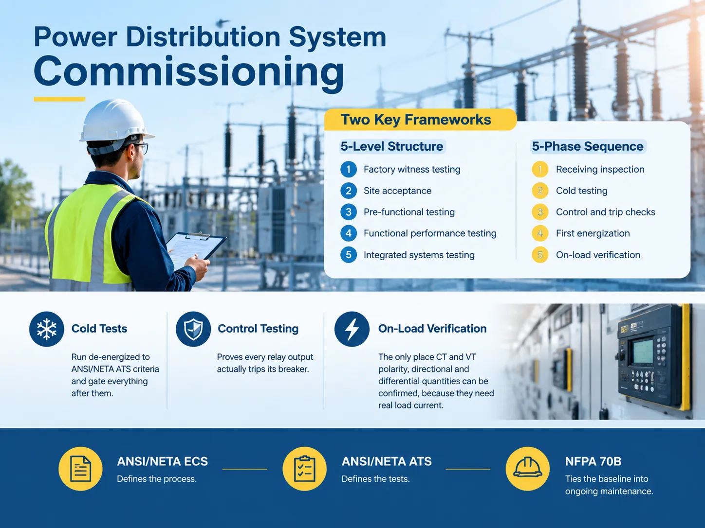
Commissioning is a portable concept that includes acceptance testing as a part of its framework but may not be limited to it. Thus, it also covers such activities as project review in terms of design and installation specifications, functional tests for every system, integrated testing for all systems, and transferring the documents necessary for the commissioning process. The process is being defined according to ANSI/NETA ECS, the Standard for Electrical Commissioning Specifications that work together with ATS without replacing it.
There are two important additions that can surely help understand the commissioning process: the first one is ASHRAE Guideline 0 that outlines the general commissioning process, and the second one is NFPA 70B documentation relevant to electrical equipment maintenance that links this stage of the project with the maintenance phase.
Whatever technical details you might use in your commissioning project, one thing defines its success: the independence of the commissioning authority (CxA). Actually, in case of mission-critical projects, CxAs usually work as independent professionals hired by the owner rather than by the contractors so that there is no possibility of the parties being involved in the same project history. The same procedure is relevant for acceptance testing where another independent contractor is employed.
The Five Commissioning Levels
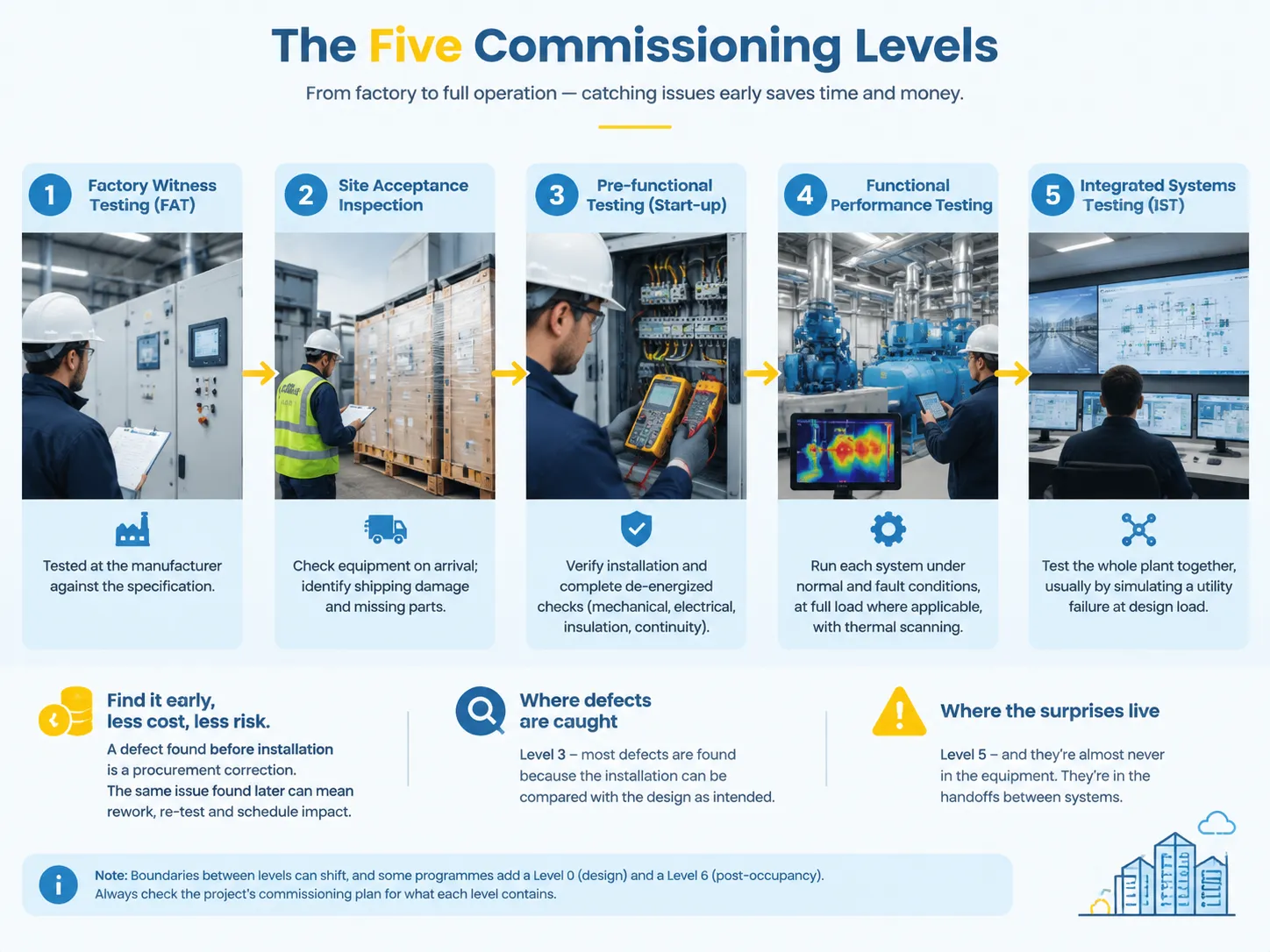
This is the framework most commonly used on data centre and industrial electrical projects, and it is the one behind the “stages of commissioning” question.
| Level | Name | What happens |
|---|---|---|
| Level 1 | Factory witness testing (FAT) | Witnessed test at the manufacturer before shipment, against a protocol written into the bid specification |
| Level 2 | Site acceptance inspection | Equipment inspected on arrival against the specification; shipping damage and missing parts identified |
| Level 3 | Pre-functional testing (start-up) | Installation verified and de-energized checks completed: mechanical and electrical inspection, insulation resistance, continuity |
| Level 4 | Functional performance testing | Each system run under normal and fault conditions, at full load where applicable, with thermal scanning |
| Level 5 | Integrated systems testing (IST) | The whole plant tested together, usually by simulating a utility failure at design load |
Level 1 and Level 2 exist due to the fact that it is significantly cheaper to identify a defect before a piece of equipment is installed than after it is installed. For example, if the equipment has mismatched nameplate ratings at the factory, this mistake can be fixed via procurement; however, if the discrepancy is discovered at Level 5, a revision of the study, re-testing, and delay of the schedule would be necessary. Level 3 is the level where most defects are caught, because this is the first time it is possible to compare the actual installation and the design. Level 5 is the level where surprises are found, while they rarely have anything to do with the equipment itself, they are rather located in the processes of transferring responsibilities between systems.
It is necessary to mention two cautionary notes about the number of levels. The boundaries of the levels often vary between different projects, and some organizations even introduce Level 0 for design and Level 6 for post occupancy. Therefore, in order to learn about the items covered by each level, one should read the commissioning plan of the project instead of assuming that the levels are the same.
The Five Phases From Receipt to Full Load
In cases of the level framework being business-oriented, the phase framework involves essential milestones and events to consider on site. Each phase proves something important for the next one, and any failure in one of them suspends any progress instead of letting it continue with a note.
| Phase | Scope | Energised |
|---|---|---|
| 1. Receiving and pre-functional inspection | Shipping damage, nameplate against specification, foundation, alignment, torque witness marks, cleanliness and dryness, storage condition | No |
| 2. Cold / static component testing | Insulation resistance, contact and bolted-connection resistance, transformer ratio and winding resistance, power factor, insulating liquid tests, CT and VT ratio and polarity, ground resistance and grid continuity | No |
| 3. Control and functional testing | Energise control power; trip-test every breaker from every relay output; verify interlocks, annunciation and SCADA points end to end | Control power only |
| 4. Initial energization | Execute the written switching order; energise progressively from the source inward; verify phase rotation, phasing between sources and bus voltage magnitudes | Yes, progressively |
| 5. On-load verification | Apply load progressively; verify in-service CT and VT polarity, directional and differential quantities; infrared survey under load | Yes, loaded |
Ordering processes should not be labeled convenience for the purpose of understanding the reliability of a fault. Nondestructive testing must be performed before proof testing for overpotential. A proof test can only be performed on equipment which has passed all the checks before it. If a cold test is failed, it will not be possible to instrument it until a later time. Phase 3 gets conducted in this phase since it is the only phase at which it can be checked that a relay output performs the task of opening the breaker or operating a lockout relay or lifting a target.
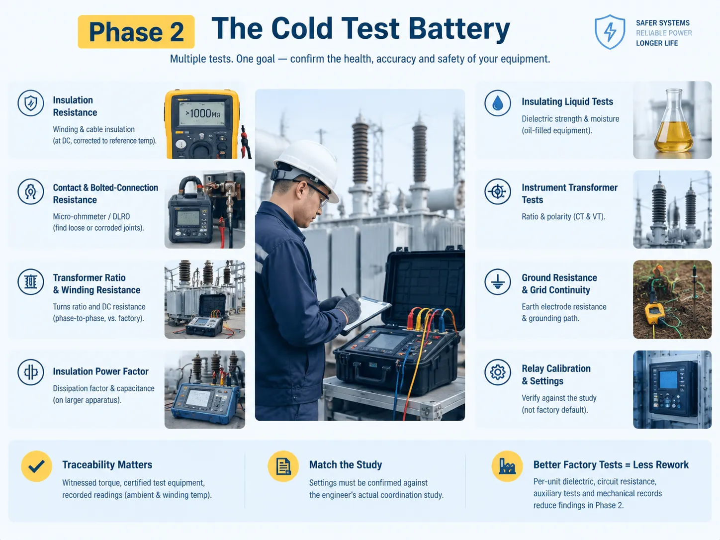
Phase 2 in Detail: The Cold Test Battery
Being the entire section’s biggest individual block, work is carried out while the equipment is de-energized in compliance with the NETA ATS guidelines. The tests performed turn into a battery of tests instead of a checklist since each test provides separate answers about the same equipment.
- Insulation resistance is assessed. The condition of winding and cable insulation is established applying DC voltage appropriate for the equipment class, correction is made to the result to allow comparison with reference temperature data.
- Contact and bolted connection resistance is checked. Measurement of micro-ohm meter or DLRO takes place between the breaker contacts and bus connections which is the way of tracing a loose or corroded connection before it turns into a hot spot.
- Transformer ratio and winding resistance are evaluated. The correct turns ratio for tap confirmation and winding condition assessment is calculated, as well DC resistance measurements are carried out comparison with the factory report is made.
- Insulation power factor. Dissipation factor and capacitance on larger equipment are measured in configurations isolating every insulation path, bushings measurement results are compared to the nameplate figures.
- Insulating liquid tests. Dielectric strength and moisture of insulating oil is evaluated, as the oil performs the function of insulation and cooling.
- Instrument transformers tests. Ratio and polarity measurement on every CT and VT are the most important cold test, because if there is a CT in reverse mode the differential relay will not be able to operate in adequate loading conditions.
- Ground resistance and grid continuity. Measurement of ground rods resistance and checking the continuity of grounding equipment path are key things as without this point the protection system will not be effective.
- Relay voltage calibration. All protective devices are measured against the coordination study outcomes instead of factory defaults.
- Professionals differentiate between the battery of tests and the numbers provided. It has to be noted that verification should be traceable for torque values, certificates indicating the condition of the testing equipment and relevant atmospheric readings. Additionally, settings should be confirmed against the document properly signed by the engineer.
The practical aspect of equipment specification is that the quality of routine factory tests defines the rework volume that the Phase 2 will face. Equipment delivered with dielectric tests, circuit resistance readings, test results of the auxiliary circuit and all the needed mechanical operation data will face minimum inspections during cold tests. Where those records come from in the production sequence — and the order in which they are performed — is set out in this description of the switchgear manufacturing process.
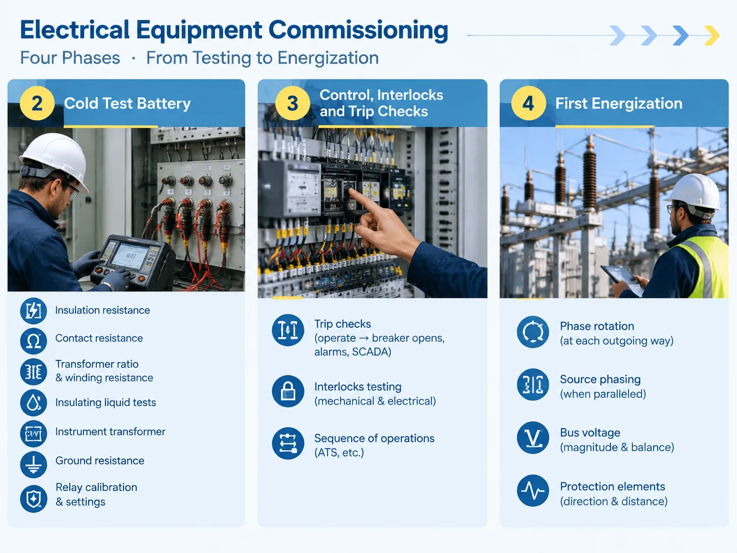
Phase 3: Control, Interlocks and Trip Checks
During Phase 3, only the control supply is activated – usually at 120 volts AC or 125 volts DC – and the scheme logic is followed while there is no power on the circuit. It is short, not that interesting, but vital.
The main operation is that of trip checking, where all relays in the system are activated physically and the entire process is witnessed. For example, even if the relay shows that the system went down the circuit breaker was opened, the lockout relay worked, the target system activated, the alarm went off, and the SCADA point changed its condition. In a system with twenty outputs disposed there are twenty tests to be performed as opposed to ten in case of one test involving several outputs.
Simultaneously with the trip checks, tests of interlocks and the sequence of operations take place. Mechanical and electrical interlocks are tested to make sure they operate according to the original idea including testing them by attempts of failure, i.e. closing the breaker while the earthing switch is closed, opening the compartment with energized circuit etc. When the plant uses an automatic bus transfer the sequence of operations is checked step by step at control voltage, before it is actually put into operation.
Phase 4: First Energization
This single task in the project presents a major risk to the project, and it is accomplished through paperwork instead of relying on judgement. A signed switching order which is reviewed before the day sets the sequence for the energization process starting from the power generator – first the incoming source, then the busbar, and finally each outgoing line one after another until the proper checks have been done.
Phase checking is accomplished in this stage of the project through four different verifications that can be obtained only at this point:
- The verification of the phase rotation at the outgoing line. If the starting of the motor is unsuccessful and wrong reversing takes place, this is the fault of the electrical team.
- The verification of phasing between the sources to make sure that the sources are not connected to the busbar at the same time in case two supplies can be connected in parallel or charging.
- The bus voltage check in terms of its magnitude as well as the voltage level comparison with the acceptable values with respect to tap and ratio calculations.
- The verification of the direction and distance protection which can be done only if the necessary data is collected.
Phase 5: On-Load Verification
The monitoring of the load is done in a gradual manner to ensure the integrity of each individual step of the procedure before going for the next level of loading. This is the only stage of the process whereby the most essential parameters of the protection procedures could be checked, as without the load applied there will be no genuine load current flowing in the system.
Both polarity and ratio of the working CTs and VTs is checked where measured current and voltage are being cross-checked, no drawing is used for that. The same has to do with directional and differential facilities where we can verify their restraint and operate values in accordance with the working load values, which makes it possible to explain the case when the differential schemes otherwise faultless in Phase 2 might not work, and Phase 5, and vice versa. Voltage drop and phase equality between the parts of the distribution are measured under sufficient loading. Also, infrared imaging is used at the stage of the testing since infrared scanning of the unloaded device may not locate any problems.
Thermal imaging should be understood separately as this is the final chance to find connection defects before they turn into the failure state. The bolted connections could perform well on the resistance test but still can appear to be hot when the device is working, which is something that is missing from condition tests.
The Five Stages, Seven Steps and Eight Stages Question
There are varied estimates from different sources. They all, however, refer to the same mechanism, but in varying levels of detail. Rather than trying to create a standard number, here is how the different systems relate to each other.
| Count | What it usually refers to |
|---|---|
| 5 levels | FAT, site acceptance, pre-functional, functional, integrated systems testing |
| 5 phases | Receiving inspection, cold testing, control and functional testing, initial energization, on-load verification |
| 6 stages | The project-level sequence used in ASHRAE-style commissioning: pre-design, design, construction, verification, and handover with training |
| 7 steps | Often a manufacturer or contractor’s own procedure for a single equipment type, such as a switchgear start-up sequence |
| 8 stages | Usually the five levels plus design review, documentation and post-occupancy monitoring |
It is very important to choose the methodology for your project charter wisely, not simply the one with the most steps. The key here is to make sure that each step has gates, that is, at the end of each phase, results are assessed before starting the next step. For instance, a seven-step methodology with well-defined gates is much better than an eight-step one that relies on good luck.
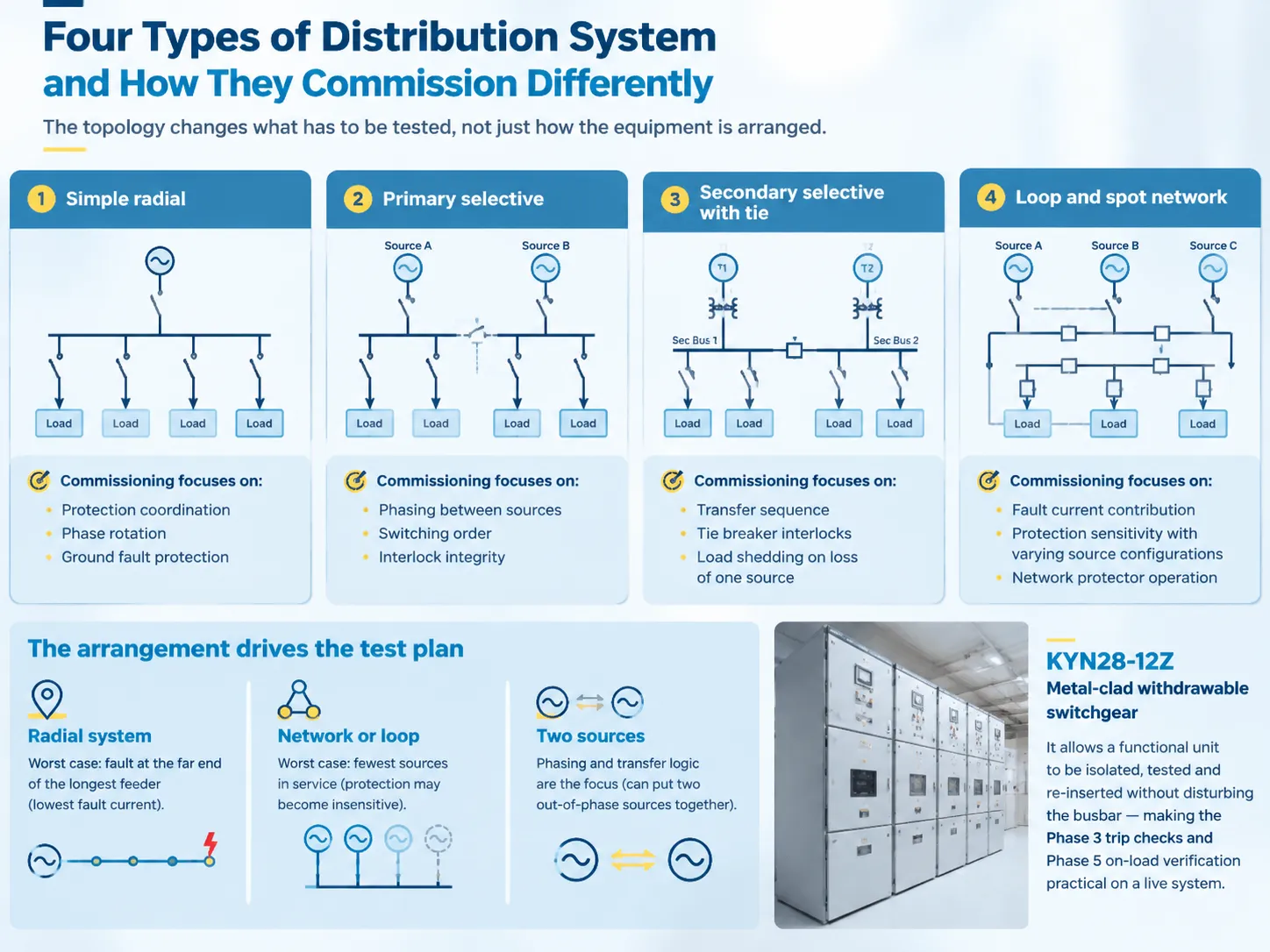
Four Types of Distribution System and How They Commission Differently
The topology changes what has to be tested, not just how the equipment is arranged.
| Arrangement | Characteristic | What commissioning focuses on |
|---|---|---|
| Simple radial | One source, one path to each load | Protection coordination, phase rotation, ground fault protection |
| Primary selective | Each load can be fed from either of two primary feeders | Phasing between sources, switching order, interlock integrity |
| Secondary selective with tie | Two transformers, each with its own secondary bus and a tie breaker | Transfer sequence, tie breaker interlocks, load shedding on loss of one source |
| Loop and spot network | Multiple sources feeding a common bus, or a loop with sectionalising | Fault current contribution, protection sensitivity with varying source configurations, network protector operation |
The design influences the test scheme since each topology has its distinct worst scenario. In the case of a radial system, worst situation occurs when a fault develops at the last position along the longest feeder, where the fault current is at its minimum. For a network or a loop, the worst case occurs when the system has the least number of active sources, as this is the way to mitigate protection. And in any system with two sources, the commissioning work is concerned mostly about phasing and transfer logic, since these are responsible for connecting the two out-of-phase sources.
The primary switchgear that carries the incoming supply defines much of this. A metal-clad withdrawable arrangement such as the KYN28-12Z armored withdrawable metal-enclosed switchgear exists precisely so that a functional unit can be isolated, tested and re-inserted without disturbing the busbar — which is what makes the Phase 3 trip checks and the Phase 5 on-load verification practical on a live distribution system.
The Documentation Package
Commissioning leads to a deliverable product, which is why commissioning is crucially important. In the absence of the deliverable, there can be no baseline. Without a baseline in place, the maintenance tests on the asset cannot be compared against anything in future stages of the asset’s life.
- Commissioning plan and script for testing indicating acceptance criteria being published before the tests.
- Checklists that were turned over by the construction company/contractor after the work was done.
- Acceptance test reports indicating measured values, temperatures of the environment and the equipment, and details on the calibration of instruments.
- Defects log that is kept throughout the whole commissioning process and confirmed after conducting the tests again.
- Relay settings and the layout study made and saved down to “as-built” values.
- Drawings and schematics keeping the real picture of what was done on a project.
- User manuals for technicians including spare parts list and other documents accompanying a device.
- Records indicating what training has been accomplished by the technicians that are supposed to operate the equipment including the source of training and how often the training take place.
Where Equipment Suppliers Fit
It is important to be precise about the boundary, as it is often unclear in tender documents.
A switchgear and substation supplier provides tested equipment along with the relevant documentation: type test report, routine test report for a specific unit, materials tests etc. This is the beginning of Level 1 and the first part of Phase 2.
However, the manufacturer does not perform commissioning activities. The commissioning authority is the engineer. Design evaluation, installation inspection, equipment operation testing, integrated testing and independent acceptance testing are carried out by the engineer of record, CxA and independent testing laboratory. In any project where the result matters, these functions must be clearly separated from the manufacturer’s function. What is allowed is factory witness testing, participation in the first energization and provision of the necessary documentation to ensure smooth operation of another company’s testing organization.How that support is scoped sits alongside the equipment offering on the service page.
Another boundary to take note of is that the manufacturer cannot serve as the commissioning agent as part of any project with a known and valued outcome.
FAQ
What are the 5 stages of commissioning?
In the context of electric power, the five stages usually refer to five commissioning levels, which include factory witness testing, site acceptance testing, pre-functional testing, functional performance testing, and integrated systems testing. Another chronology of five phases starts from the phase of receiving and pre-functional inspection and ends with the phase of on-load testing. Each framework provides a different view of the same procedures; one is based on who does what at what time, while the other organizes what needs to be done by when it should physically take place. Make sure of your project’s commissioning plan before using one of the frameworks.
What are the 7 steps of commissioning?
The seven-step electrical commissioning procedure is not an established norm that is consistent from one country to another. Even if seven steps are mentioned, they usually refer to the start-up routine as designed by the manufacturer or contractor for a specific type of equipment. The seven steps usually include such tasks as receiving, inspecting, mechanical testing, testing of insulation resistance, testing of contact resistance, testing of the relay, and testing of control circuits. The seven steps are just some of the phases outlined in the five-phase procedure.
What are the four types of power distribution systems?
According to the topology of the system, such network types can be divided into simple radial, in which one source feeds one route to each consumer; primary selective, allowing consumers’ supply through either of the two primary feeders; secondary selective, where there are two transformers, two secondary busbars and a circuit breaker in between; as well as loop or spot network, which is a common bus supplied by multiple sources or a network loop with sectionalising elements of the circuit. In some authors’ view, double-ended system is an alternative type in the case of secondary selective. Each of the system types has different commissioning focus in the process: radial networks focus on protection coordination, while the systems with two sources – on switchboard and transfer system performance, whereas the network networks focus on sensitivity of protection.
What are the 8 stages of commissioning?
Generally, eight stage processes consist of five phases as well as the stages of project planning, usually comprised of design review, documentation, post-occupancy monitoring and other phases of factory testing, site acceptance, pre-functional, functional, integrated systems testing. Since there is a variation of boundaries among processes on programs, it is not so important to know their number but to follow the gauging where the stage is recognized as completed when the outcome of the process has been verified.
What is the difference between acceptance testing and commissioning?
As a whole, the eight step process has five phases and consists of the project planning phases which include design review, documentation phase, post-occupancy monitoring phase. Other processes can include factory tests, acceptance phase, pre-functional phase, functional phase and the stage of integrated kind. Though the number of stages of the processes can vary on the programs, it is less important than the tracking of the stage of completion and the point at which the phase is defined because its results are confirmed.
Why can’t directional and differential protection be fully tested before energization?
This requires actual load current for the validation of the behavior of these components. Cold testing can confirm whether or not the relay has functioned, whether or not the settings of the device correlate with the plan for coordination and whether or not the relay trip signals the correct circuit. Cold testing is not capable of confirming whether or not the CT polarity is correct in service, and whether or not the quantities of restraint and operation behave according to the design because it involves no real electric load during the cold state. Phase 5 was invented to make it possible to check the CT polarity and polarity of VT in service and directional and differential checking under load conditions and make infrared image while there is load for the last time to find the device that passed every test but works improperly.
References
- NFPA — NFPA 70, National Electrical Code
- IEEE Standards Association — IEEE power system protection and testing standards
- International Electrotechnical Commission — IEC 62271 series, switchgear and controlgear
- UL Solutions — electrical equipment testing and certification
- IEC Webstore — IEC 62271-203, gas-insulated metal-enclosed switchgear above 52 kV
Conclusion
The commissioning stage turns the equipment into a working system, but it only works when everything is deployed correctly. Each step involves cold testing prior to energising, control and trip testing prior to putting the load on the equipment, energising under a formal written order, and then on-load testing as the final stage that cannot start if previous steps are not complete.
There are three critical points. First, make sure not to confuse commissioning and acceptance testing, as the former encompasses the latter but not vice versa. Second, have real trip testing instead of relying on a single test because an untested relay output does not provide confidence that protection works. Third, consider the set of documents as a deliverable.
By performing all operations in the right sequence, the sign-off will be a formality. If something goes wrong in the commissioning process, it will undermine the expected performance of equipment at least in the following two years. The best way to check how knowledgeable a supplier is, is to see what voltage, configuration, and equipment had been energised earlier.