
Two quotes for the same plant can look very different. One supplier offers a fixed capacitor bank at a modest price; another proposes an APFC panel that costs noticeably more for the same kVAR. Both will raise power factor at full load. The real difference shows up at 2 a.m., on Sundays and during shift changes — when the load drops and the capacitors stay behind.
This guide looks at the distinctions between the two based on factors that help complete the purchase: the extent a reactive load fluctuates, the performance during light load, overall cost over the lifespan, and change of harmonics as an important factor. For the illustrations in this comparison, we used Eaton’s UniPak, UniPak Filter, and AutoVAR600 and the calculations for two shifts for the visual presentation of numbers for support. As for the kVAR sizing formula, please refer to our prompt guide on how to size a power factor correction capacitor bank.
Quick answer: A fixed capacitor bank should be used when the reactive load stays unchanged throughout the processing operation — manufacturing processes, pumping stations, considerable electric motors functioning uninterrupted — or when the capacitor can be switched together with the electric motor needing its service. Automatic capacitor bank (APFC panel) should be a choice when the demand for reactive power alters from day to night or seasonally. The crucial figure to determine is the gap between the maximum and lowest reactive loads rather than the total kVAR consumption: if the fixed bank has been sized according to the maximum load but exceeds the kVAR consumption during light load, it will need an automatic switching or minimum fixed capacity paired with automatic steps.
APFC Panel vs Fixed Capacitor Bank: Key Differences
Both products use the same building block — low-voltage power capacitors with discharge resistors and fuse protection. What changes is whether anything decides how much of that capacitance is connected at a given moment.
| Aspect | Fixed capacitor bank | APFC panel (automatic capacitor bank) |
|---|---|---|
| Compensation | One block of kVAR, all in or all out | Several capacitor steps switched in and out |
| Control | Manual switch, breaker, or interlocked with a motor starter | Power factor controller reading a CT on the incomer |
| Best-fit load profile | Steady, 24/7 or switched with one load | Varies by shift, process or season |
| Light-load behaviour | Can over-correct and push the plant leading | Disconnects steps to hold the target PF |
| Accuracy | Correct only at the load it was sized for | Limited by the smallest step |
| Typical location | At a large motor, or at a feeder with a constant base load | Main LV switchboard or a major sub-board |
| Wearing parts | Few (fuses, switch) | Capacitor-duty contactors, controller, fans |
| Equipment cost per kVAR | Lowest | Higher (controller, CT, contactors, larger enclosure) |
| Harmonic environments | Can be supplied detuned (one reactor set) | Can be supplied detuned (a reactor per step) |
| Response time | None — it does not track the load | Seconds to minutes per step (contactor-switched) |
What Is a Fixed Capacitor Bank?
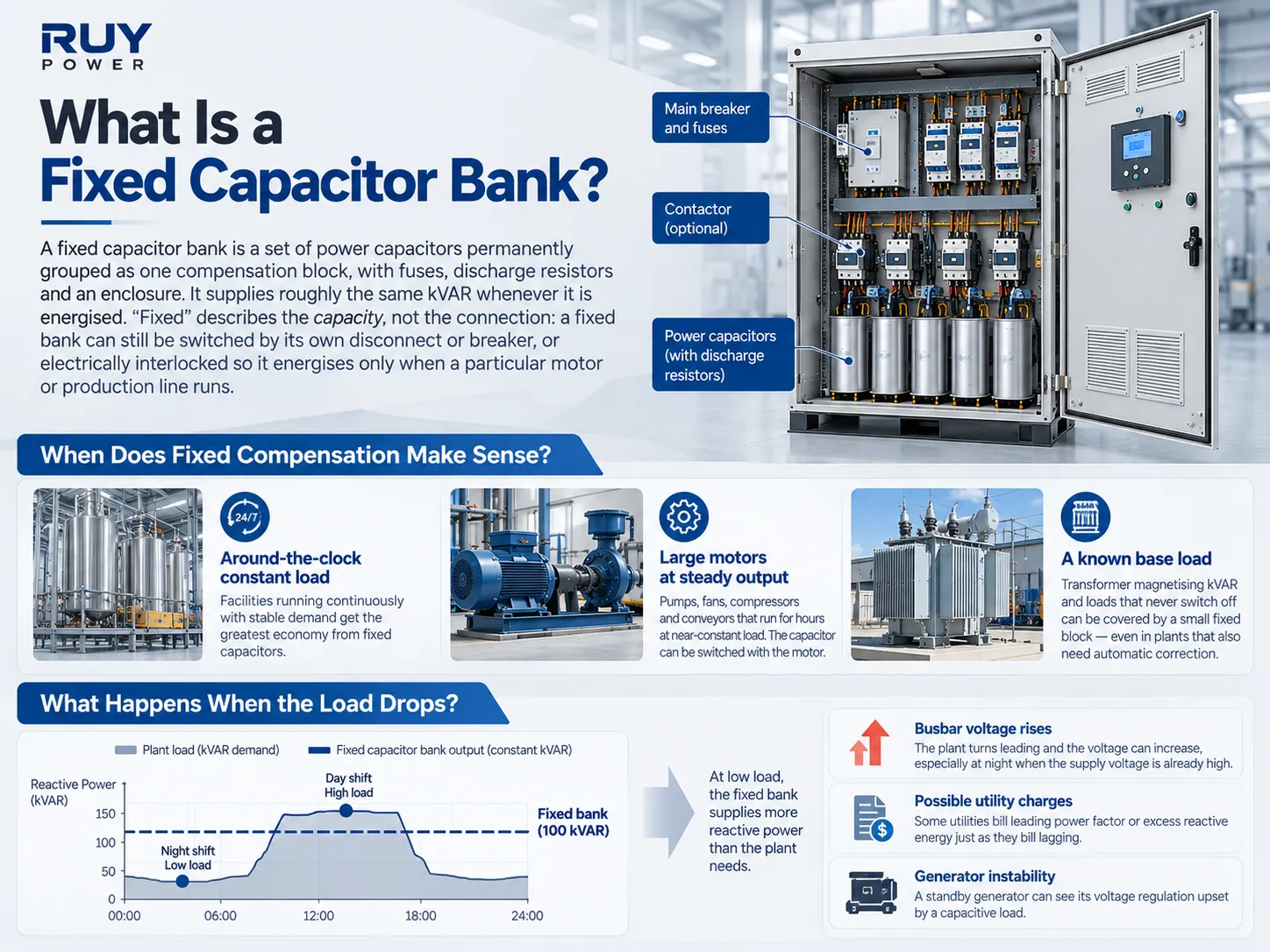
A fixed capacitor bank consists of a collection of power capacitors permanently assembled into one compensation module that contains fuses, discharge resistors, and an outer shell. It provides approximately the same kVAR when it is turned on. “Fixed” characterises its capacity rather than the method used to connect it, and the fixed bank can still be switched using its own disconnect or breaker or electrically interlocked in a way that makes it switch on only when a specific motor or production line works. The plant engineer’s guide published by Eaton gives a precise account of this hypothesis: a fixed bank is the cheapest, but at the same time is less flexible and requires its own switches or circuit breakers.
When Does Fixed Compensation Make Sense?
- The facility that operates continuously with a load that does not change constantly gets the highest economy from the permanent capacitors, according to Eaton’s guide. At the same time, organizations running on an eight-hour schedule need a higher amount of switched capacitors.
An installation at work involves motors that are operating at the same speed all the time. One can use pumps, fans, compressors and conveyors that function at close to a constant load. The capacitor that is on when the motor is operational compensates for the load of the motor making power supply easier for the motor itself. The capacitor should not exceed the allowed kVAR that the manufacturer allows in the case schematic.
A steady base load calculated based on the kVAR of transformer magnetising runs in case of all the loads that do not switch off can be covered with help of a small fixed block of capacitance even if a plant would require automatic compensation simultaneously with this block.
What Happens When the Load Drops?
A fixed capacitor produces its kVAR output no matter what the plant is doing. When motors stop but the capacitor bank is still in circuit, the capacitor gives off more reactive power than what is being consumed. The excess is shunted back into the source, making the plant leading, which leads to three outcomes: 1) The bus voltage goes up (and the highest increase takes place at night, as the voltage is already at a high level); 2) Some power companies charge for leading power factor/overreactive energy, just as they charge for lagging; 3) A site supplied by a stand-by generator can see its voltage regulation disturbed by a reactive load. This is the main reason that a fixed capacitor bank designed for maximum load does not work for a plant that operates in two shifts, as seen in the example below.
How Does an APFC Panel Work?
An APFC panel (automatic power factor compensation panel, also marketed as a capacitor compensation cabinet) provides intelligence to the capacitor bank. The current transformer installed on the incoming line and the voltage at the busbar enable the power factor controller to establish the total requirements of reactive power of the plant. The controller uses the contactors for capacitor switching to maintain the actual power factor at or near the given setpoint, usually between 0.95–0.98 lagging.
Automatic Switching and Capacitor Steps
The way in which an automatic capacitor bank conforms to the load depends on two design features:
Magnitude of steps. The smallest step is the one that determines the precision of the system. If the smallest step is greater than the needed reactive power at low loads, the controller can only be able to select between too much or too little compensation, and binary combinations (like 1:2:4) achieve better precision with fewer contactors.
Switching time. The capacitor must be discharged before it can be reconnected back, so there is a discharge time implemented (in most cases several tens of seconds). This leads to the conclusion that capacitor banks that use contactors are most efficient in case when the load changes during minutes or hours, not seconds.
Limitations of Standard APFC Panels
- Speed. Welder machines, elevators, compactors and other gadgets receive constant modifications which is why contactors are not suitable for them – instead, they should be equipped with either thyristor controlled capacities or an SVG. Our pillar guide compares these options.
- Wear and maintenance. Contactors, propellers and the control mechanism are components that wear out over the course of utilization hence a malfunctioning contactor or blown fuses cause the reduced amount of available k VAR in a quiet way; therefore, it is highly recommended to test the currents coming from contactors from time to time.
- Capacitors only add leading kVAR. Capacitators will help only in terms of generating leading k VAR hence in case when load is already leading (in case of a lightly loaded room or long wires) the APFC panel can only disconnect the capacitators but can’t consume excess k VAR.
- CT location matters. The CT should consist of total load together with the current coming from the capacitors; a CT situated on the wrong side causes CT hunting or wrong power factor results.
Eaton UniPak vs AutoVAR: Real-World Examples
Eaton’s low-voltage power factor correction range is a significant reference as it has introduced an individual product for each architecture. The tables provided below are taken from Eaton’s US product pages (60 Hz, North American voltages); RUY Power is not in a partnership with Eaton and only mentions these products to clarify the categories.
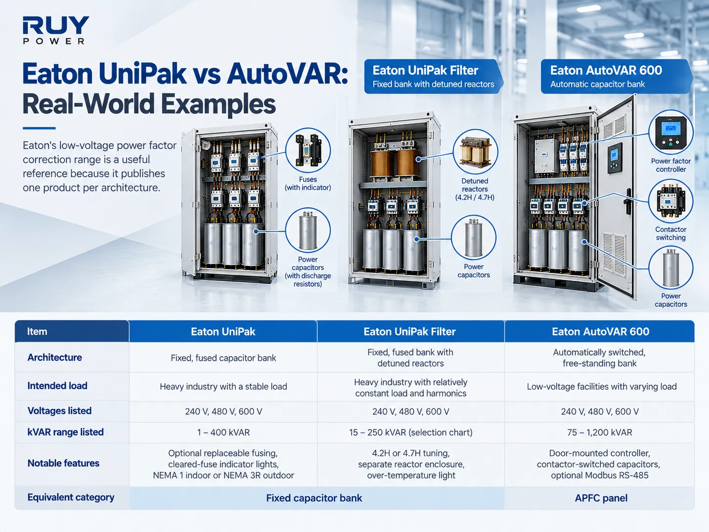
| Eaton UniPak | Eaton UniPak Filter | Eaton AutoVAR 600 | |
|---|---|---|---|
| Architecture | Fixed, fused capacitor bank | Fixed, fused bank with detuned reactors | Automatically switched, free-standing bank |
| Intended load | Heavy industry with a stable load | Heavy industry with relatively constant load and harmonics | Low-voltage facilities with varying load |
| Voltages listed | 240 V, 480 V, 600 V | 240 V, 480 V, 600 V | 240 V, 480 V, 600 V |
| kVAR range listed | 1–400 kVAR | 15–250 kVAR (selection chart) | 75–1,200 kVAR |
| Notable features | Optional replaceable fusing, cleared-fuse indicator lights, NEMA 1 indoor or NEMA 3R outdoor | 4.2H or 4.7H tuning, separate reactor enclosure, over-temperature light | Door-mounted controller, contactor-switched capacitors, optional Modbus RS-485 |
| Equivalent category | Fixed capacitor bank | APFC panel | |
Eaton UniPak Fixed Capacitor Bank
In most cases, inquiries about Eaton UniPak fixed capacitor banks come from engineers seeking compensation for either one significant load or a steady line. Eaton promotes UniPak as a heavily industrialized solution for fixed capacitance where this type of solution is appropriate. This means that UniPak is applied when the reactive demand is determined and likely to be used on the motor or the line with the steady power consumption rather than at the input of a plant with a varying load.
Eaton AutoVAR Automatic Capacitor Bank
Eaton’s AutoVAR 600 is a self-contained automatic bank. The device’s controller oversees the operation and connects or disconnects capacitor steps in accordance with the desired value of the power factor. Minimum power of 75 kVAR of the AutoVAR 600 indicates where these types of automatic banks are applied, namely in the main switchboard or point of service.
What About Eaton UniPak Filter?
The UniPak Filter is the part that demonstrates that the common belief is not true. It is a fixed bank that has detuned reactors which help capacitors to withstand the troubles from networks having lots of harmonics. The tuning of 4.2H and 4.7H way means the harmonics of the tuning of the reactor and capacitor which is situated under the 5th harmonic which equals about 252 Hz and 282 Hz on a 60 Hz system. To sum it up, we can say that harmonic protection is not the reason why you should choose automatic instead of fixed as both configurations can be detuned.
Fixed vs Automatic Capacitor Bank: A Load-Variation Example
Take into consideration a manufacturing facility that operates in two shifts and records a displacement power factor of 0.80, irrespective of load conditions. The goal is to attain a power factor of 0.95. The peak load experienced during the day shift is 200 kW, during the evening shoulder period – 120 kW and base loads at night – 50 kW. During the day shift, about 84 kVAR worth of capacity is required. Comparing the options for compensation, the buyer looks at the two alternatives, both rated at 90 kVAR capacitance value:
Option A: a 90 kVAR fixed capacitor bank connected permanently.
Option B: a 90 kVAR automatic power factor regulator (APFC) panel with 6 steps of 15 kVAR each, automatically regulated at the power factor value of 0.95.
| Operating state | Load reactive demand | Option A: fixed 90 kVAR | Option B: APFC, steps in service |
|---|---|---|---|
| Day shift, 200 kW | 150 kVAR | PF 0.958 lagging | 90 kVAR → PF 0.958 lagging |
| Evening, 120 kW | 90 kVAR | PF 1.00 (fully cancelled) | 60 kVAR → PF 0.970 lagging |
| Night, 50 kW | 37.5 kVAR | PF 0.69 leading — 52.5 kVAR pushed back to the supply | 30 kVAR → PF 0.989 lagging |
Sinusoidal, balanced loads; capacitor output voltage is in its capacity. The real behavior of the controller is based on switching hysteresis, configurable settings, and steps configuration. Use the kVAR calculator to perform your latest response task.
When running in rated loading conditions both solutions cannot be distinguished at all — which is why the comparison of quotes based on one operating point can be misleading. At night the stationary bank turns the 0.80 lagging facility into a leading one with a power factor of 0.69 and with apparent power of approximately 72 kVA when dealing with 50 kW of load, meaning it has a less than zero performance in terms of power factor compared to no correction (0.80). The APFC controller just shuts down four steps.
At the same time, these numbers help us see an alternative solution that is often forgotten by many consumers suggesting another solution: fixed base equipment plus automatic topping up. At night the load requires about 21 kVAR to have a power factor equal to 0.95 and consumes 37.5 kVAR, thus it means that the fixed size of approximately 30 kVAR can be connected 24/7 without turning the power factor of the facility into a leading one, while the output of the smaller automatic part of the operation (in this case it’s 4 x 15 kVAR) is activated during the day shift. This means that this solution has the same efficiency of the option B with fewer maintenance requirements.
Which Capacitor Bank Has the Lower Total Cost?
On purchase price, the fixed bank wins almost every time. On total cost, it depends on what the bank does during light-load hours.
| Cost element | Fixed capacitor bank | APFC panel |
|---|---|---|
| Equipment | Lowest per kVAR | Higher: controller, CT, step contactors, larger enclosure |
| Installation | Needs its own disconnect or interlock for each location | One connection at the main board covers the whole plant |
| Maintenance | Fuses and capacitor checks | Plus contactors, fans and controller settings |
| Tariff savings | Full savings only while load matches the bank | Holds the target PF across shifts |
| Cost of a wrong choice | Leading PF, overvoltage, possible leading-PF charges | Paying for steps and switching the load never uses |
In his summary of sources on electrical equipment, Eaton points out the trade-off where fixed and individual banks are the cheapest, while automatic banks come at a higher price tag, but serve well under variable load conditions and keep voltage levels down. The payback on such systems may vary from one installation to another.
Both situations where you may want to wait for the alternative technology are the following:
the load being affected by harmonics rather than having a low power factor — the presence of distortion (e.g. the use of rectifying or large electric motors) means that capacitors are of no help;
the load variation is too fast for contactors to respond (e.g. on welding lines and winches) and a thyristor-alternating bank is more suitable for such instances.
Harmonic Risks: Do Both Types Need Detuned Reactors?
Indeed — a network with appreciable harmonics does not absolve one from the need for a detuned reactor, irrespective of whether one has fixed or automatic compensation. A capacitor bank of either type creates resonance in parallel with the transformer. The guideline in Eaton refers to a simple rule of thumb: a harmonic filter is almost always needed if the amount of three-phase nonlinear load exceeds approximately 25% of the main transformer kVA; below about 15%, basic capacitor banks can be used; the situation between these two figures is more complex.
The difference between the two systems is that the behavior of resonance is different. In a fixed bank, a bank has only one resonant frequency which can be calculated only once. In automatic banks, the resonant frequency changes every time the capacitor step is switched on and off, so a combination that is fully safe with two steps can be close to resonance with the 7th harmonic, so the detuned automatic systems have to use a reactor with each of the capacitor steps. The resonance calculation is covered in our power factor correction capacitor guide.
How to Select the Right Capacitor Bank for Your Plant
| Site condition | Likely choice | Check before ordering |
|---|---|---|
| Constant 24/7 load, low harmonics | Fixed capacitor bank at the board | Light-load kVAR never falls below the bank rating |
| A few large motors at steady output | Fixed capacitors switched with each motor | Motor maker’s maximum kVAR (self-excitation) |
| Load varies by shift or season | APFC panel | Smallest step vs night-time demand |
| Steady base load plus variable production | Fixed base + APFC top-up | Fixed part ≤ minimum reactive demand |
| Nonlinear load > 15–25% of transformer kVA | Detuned fixed or detuned APFC | Harmonic measurement and resonance check |
| Load changes within seconds | Thyristor-switched bank or SVG | Required response time |
The most valuable input to have is a load log, specifying kW, kVAR, and power factor at the main incomer, which must be done over a minimum period of a week to capture nights, weekends, and start-ups. The log will usually provide the answer to the fixed vs automatic power factor correction question. To this, add system voltage, frequency, transformer rating, and impedance and a list of drives, UPS, and rectifiers — the full RFQ checklist is in our pillar guide.
RUY Power GGJ: Automatic Compensation for LV Distribution
RUY Power’s GGJ low-voltage capacitor compensation cabinet is an APFC panel for plants whose reactive demand changes through the day:
- The device operates at a voltage of 0.38–0.66 kV and has a rated capacity of 1–600 kVAR with 1–16 control circuits.
Power frequency for the cabinet is 50 Hz; however, there is an option to manufacture the panels for a frequency of 60 Hz.
The GGJ cabinet offers adjustable switching time of 1–150 s, continuous and automatic operation, and can operate at 0.85-1.1 of rated voltage.
The smart controller provides the display of power factor in real time and protects against overvoltage, exceeding current limits, overcompensation and phase failure.
The phase compensation scheme can comprise mixed or separated phase correction in case of networks with unbalance.
The GGJ panel can monitor three-phase voltage, current and power as well as harmonics of 2nd -25th orders, data can be sent to RS-232 and RS-485 interfaces.
The GGJ cabinet can be used with 130-600 kVA transformers and the ordering time is 15-30 days
The configuration of the device and its parts is made to every single project, load diagram and harmonic data should be sent and the configuration scheme is confirmed at the engineering department of RUY. The GGJ cabinet can be supplied alongside RUY’s GGD, GCS and MNS low-voltage switchgear as one coordinated board.
Frequently Asked Questions
Are APFC and capacitor bank the same?
That’s not entirely accurate. A capacitor bank is found in APFC panel, but the opposite is not true. An APFC panel consists of a current transformer, power factor controller and switched capacitor steps. Therefore compensation changes with the load. A fixed bank delivers the same kVAR every time it is connected.
What are the two types of capacitor banks?
There are two major kinds of low-voltage power factor correction i.e. fixed capacitor bank and automatically switched capacitor bank or APFC panels. Any of them can be provided with detuned reactors in case of networks with harmonics. These two types can be combined as a fixed base with automatic stepping.
Why is the capacitor used in the APFC panel?
Inductive loads such as motors and transformers are responsible for drawing reactive energy but with its inability to produce suitable magnetic energy. To combat this, capacitors produce and supply leading reactive power locally which then helps to reduce how much reactive current needs to be provided from the utility. This reduces displacement power factor and kVA demand and protects upstream cables and transformers.
What is the APFC panel used for?
An automatic capacitor bank that helps to maintain the power factor at a particular level even when the load fluctuates in commercial or industrial installations. The function of the panel is to eliminate the penalties for the power factor and kVA or kVAR charges, free up the capacity of the transformer and cable, and prevent the over-correction that is caused by a fixed bank at low load.
Is the Eaton UniPak a fixed or automatic capacitor bank?
The Eaton UniPak is a fixed, fused low-voltage capacitor bank intended for stable industrial loads. Eaton’s automatic equivalent is the AutoVAR 600, and its detuned fixed version is the UniPak Filter.
What happens if a fixed capacitor bank is too large?
If the load is lower than the value use for bank sizing, plant becomes leading: voltage at busbar increases, some utilities impose charges for leading power factor or excess reactive energy, and generators at standby may get into problems with voltage regulation. Size the fixed part according to the least reactive requirement, or alternate it with the load served by this part.
Can I combine a fixed capacitor bank with an APFC panel?
Yes. A fixed block sized to the plant’s constant base load, plus automatic steps for the variable part, is a common and cost-effective arrangement. Make sure the APFC controller’s CT sees the fixed bank’s current too, so it does not over-correct.
Conclusion: Match the Bank to the Load Profile
A capacitor bank that is fixed and an Automatic Power Factor Correction (APFC) panel use identical capacitors and produce the same outcomes at maximum load. The two devices diverge when the load declines, where a fixed capacitor bank is the most economical option for applications with a stable reactive power consumption by the plant, while a system with automatic switching, or fixed arrangement that can be topped up automatically, needs to be utilized for systems with variable loads between periods of operation.
Get a GGJ APFC Panel Configured for Your Load
Send RUY Power your system voltage and frequency, transformer rating, peak and minimum kW, existing and target power factor, and any harmonic measurements. Our engineers will propose the step arrangement — including a fixed base section where it makes sense — and quote a GGJ capacitor compensation cabinet for your project. Contact RUY Power.
References
- Eaton — Power Factor Correction: A Guide for the Plant Engineer (SA02607001E, 2024). Fixed vs automatic trade-offs, load constancy, nonlinear-load screening.
- Eaton — UniPak. Fixed, fused LV capacitor bank for stable industrial loads.
- Eaton — UniPak Filter. Fixed capacitor bank with 4.2H / 4.7H detuned reactors.
- Eaton — AutoVAR 600. Automatically switched LV capacitor bank.
- RUY Power — How Do You Size and Select a Power Factor Correction Capacitor Bank? kVAR formula, calculator, resonance check and RFQ checklist.
Eaton, UniPak and AutoVAR are trademarks of Eaton. RUY Power is not affiliated with Eaton; product details are taken from Eaton’s public product pages for comparison only.