
The way that most plants recognize that they need a power factor correction capacitor is by seeing a line on their electricity bill that says “power factor adjustment”, “kVA demand”, or “reactive charge” and continues to get larger. The solution seems simple – the answer is to add capacitors; however, it is in the next three decisions that companies often incur a big expense: how much kVAR to purchase, whether to use a fixed or automatic bank, and whether or not their variable speed drives can turn the new capacitor bank into a harmonic amplifier. This guide examines those decisions in order as an engineer would approach them step by step, starting with reading the bill and proceeding to preparing the RFQ, with a worked calculation and a kVAR calculator you can use for your own load.
To put it simply, a power factor correction capacitor is a shunt capacitor (or a number of them) connected to the power supply that provides reactive power (kVAR) needed by motors, transformers, and other inductive electrical devices. In order to determine how much kVAR is needed following the formula Qc = P × [tan(arccos PF1) − tan(arccos PF2)] will help: in case of 400 kW load we will need about 221 kVAR in order to correct power factor from 0.75 to 0.95 which allows to decrease current about 21%. In the case of constant loads fixed capacitors can be used while changing loads will require an automatic power factor correction capacitor bank with step switching; and in the case of variable frequency drives, uninterruptible power supplies, or rectifiers being an important part of load, the bank should be a detuned one.
What Is a Power Factor Correction Capacitor?
Power factor is the ratio of real power to apparent power: PF = kW ÷ kVA. The real power (kW) performs the work of going to work, such as rotating shafts, creating heat, and providing light. The reactive power (kVAR) is energy borrowed by motors and transformers every cycle and then returned back, without performing useful work. However, reactive power has to go through the whole wiring so it generates additional load on current and apparent power (kVA) as well.
Any method of getting rid of that reactive power is power factor correction. The principle of work is simple: since the action of the capacitor is to draw leading current while the action of the induction motor is to draw lagging current, the two become linked through their function.
How Does a Power Factor Correction Capacitor Work?
Let’s take a three-phase induction motor as an example. Assume that the motor is working in a partial load. The magnetizing current is practically constant regardless of the load of the shaft, which due to a small load makes the reactive power component make up a big proportion of the current. Therefore, the power factor is low, frequently being within 0.7–0.8. When the capacitor connected in parallel comes into play, now we have a certain amount of power very effectively delivered to the apparatus. There is a constant amount of power consumed by the inductive motor.
Some physical principles are to be taken into account when choosing an appropriate capacitor:
The output of the capacitor depends on the square of voltage. Q = Qrated × (U ÷ Urated)². For example, a 50 kVAR, 440 V capacitor operating in a 400 V system produces approximately 41 kVAR.
The output of the capacitor depends on frequency as well. A 50 Hz rated device will generate 20% more power on a system working at 60 Hz.
Capacitor vs Capacitor Bank vs APFC Panel
The three terms are often used interchangeably in RFQs, which is how buyers end up with quotes that cannot be compared.
| Term | What it is | Typical size | Where it is used |
|---|---|---|---|
| Power factor correction capacitor | A single three-phase capacitor unit (can or box) with internal discharge resistors | 2.5–50 kVAR per unit | Directly at a motor terminal, or as the building block of a bank |
| Power factor correction capacitor bank | Several capacitor units in one enclosure with fuses or MCCBs, contactors and busbars, switched as a fixed block or in steps | 25–1,000+ kVAR | Main LV switchboard or a sub-distribution board |
| APFC panel (automatic power factor correction panel, capacitor compensation cabinet) | A capacitor bank plus a power factor controller and a CT that switches steps in and out to track a target PF; may include detuned reactors | 50–600+ kVAR per section | Main LV board of plants with changing loads |
In IEC markets a factory-built automatic bank is formally a “low-voltage power factor correction bank” under IEC 61921; in Chinese supply catalogues the same equipment is sold as a GGJ-type capacitor compensation cabinet.
Is it Required to Apply Power Factor Correction?
Power factor correction is mandatory. The readings on your bill provide information on both demand in both kW and kVA. It means the following: if you divide kW with kVA, you can figure out power factor used for calculating costs. It is local power regulations that define all the details such as maximum demand, average time period used for calculation and if leading power factor is charged, so check the rates prior to making any calculations.
How to Measure Power Factor at an Industrial Facility
Your utility bill includes just one number in terms of monthly demand. You need to develop the bank on the basis of snapshot of the actual loads. You can do this in the following way:
Take multi-function meter of the main feeder and measure kW, kVAR, kVA and power factor (PF) during the peak load and in the light load periods.
Use the three-phase power quality meter at the main feeder for a week with constant reading every few minutes to capture night, weekend and start-up working shifts.
Collect readings of voltage distortion as well as different harmonics at the same time.
Obtain the transformer nameplate showing its rating and impedance and make up a list of all non-linear loads existing in the facility including various VFDs, UPSs, rectifiers, induction furnaces and others.
Thus, the answer to the question how to identify the correction option is not one figure but a kVAR curve.This means that the value given will help in determining the size of a bank and the number of steps of the bank.
The meter gives you one number a month. In order to size a bank, you should know the load profile linked with it. The measurement plan in practice is as follows:
1.Check the multifunctional meter of the main incomer for kW, kVAR, kVA and PF at maximum and minimum load.
2.Monitor the activity at the main incomer using a multi-phase power quality analyzer for not less than a week at intervals of 1-10 minutes so to obtain data during night shifts, weekends and during starting time.
3.Measure voltage and current THD together with harmonics measurements (3rd, 5th, 7th, 11th, 13th) simultaneously.
4.Get everything measured in the transformer rating and impedance stated on its nameplate and mention big non-linear loads such as VFDs, UPS, rectifiers, induction furnaces, welding equipment, EV chargers.
That is the practical answer to the question of how to measure the power factor correction requirements. That is how kVAR must be measured, and not in a single reading because the kVAR drawing will help to understand the bank size and the size of the steps of installation.
True Power Factor vs Displacement Power Factor
The difference between True Power Factor and Displacement Power Factor is where many PFC projects fail. Displacement PF (cos φ) is the phase angle which separates the fundamental voltage and current signals. True power factor is kW total divided by kVA total and accounts for harmons. For sinusoidal loads, true power factor and displacement power factor are the same. In case of six-pulse drive sinusoids this is not the case: the front end of the DC bus of the inverter has displacement power factor which is around 0.95–0.98, but distortion will affect true power factor and considerably lower its value.
Capacitors are used for correction of displacement power factor only. If low power factor of the facility is caused by a lot of harmonic distortions, adding the capacitors won’t increase the value by much and even make things worse. In this case, harmonic suppression must be applied (means: line reactors, passive or active filters), and not more kVAR. Be sure to understand which kind of problem you have gained before making any purchases.
Calculating Power Factor Correction Capacitor Size in kVAR
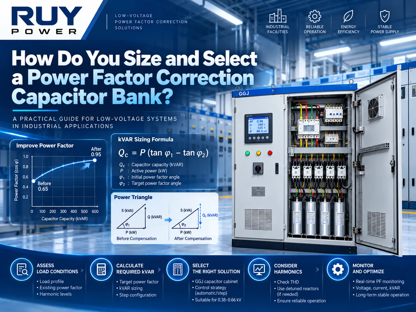
To determine the correct capacity of the capacitor to be used; the capacity is obtained by calculating the difference between the reactive power drawn by the load in the present time as compared to the reactive power drawn at the required power factor.
The formula kVAR Sizing
Qc (kVAR) = P (kW) × [tan (arccos PF1) − tan (arccos PF2)]
Where Qc is the rating of the capacitor in kVAR’s, P is the real power in kW, PF1 is the existing power factor and PF2 is the required power factor. The real power at which the operation is being corrected must be used.
Example: 400 kW Industrial Load
A facility supplied by a 630 kVA transformer with 400 kW peak demand having a power factor of 0.75. The targeted power factor being 0.95.
1. Existing reactive power: 400 × tan (arccos 0.75) = 400 × 0.882 = 352.8 kVAR.
2. Reactive power at target power factor: 400 × tan (arccos 0.95) = 400 × 0.329 = 131.5 kVAR.
3. Rating of the capacitor: 352.8 − 131.5 = 221.3 kVAR.
| Quantity | Before correction (PF 0.75) | After correction (PF 0.95) | Change |
|---|---|---|---|
| Real power | 400 kW | 400 kW | none |
| Reactive power from the supply | 352.8 kVAR | 131.5 kVAR | −62.7% |
| Apparent power | 533.3 kVA | 421.1 kVA | −21.1% |
| Line current at 400 V | 770 A | 608 A | −21.1% |
| Line current at 480 V | 642 A | 506 A | −21.1% |
| I²R losses in cables and transformer upstream of the bank | 100% | 62.3% | −37.7% |
| Loading of the 630 kVA transformer | 84.7% | 66.8% | 112 kVA released |
Assumption: equal three-phase load, fixed voltage, and special displacement power factor. The only losses seen is in cables between the supply and capacitor bank; the wires below bank are carrying the same current.
However, the facility needs to buy a bank of 240 kVAR automatic bank, and not 221 kVAR exactly. The margin will take care of the ageing of the capacitor and use the bank at lesser than allowable voltage. When capacitor bank is designed in 20 + 40 + 3 × 60 kVAR arrangement, there will be only five contactors to get 20 kVAR resolution, which is useful at nighttime. If during night time the off-shift load is equal to 120 kW at 0.70 PF Level, it needs only 83 kVAR for the load so if it gets installed bigger single fixed block capacitor it will put facility in the advance PF category supply.
Power Factor Correction Capacitor kVAR Calculator
Enter your own load to size a power factor correction capacitor bank. Add the transformer rating and impedance to run a quick harmonic resonance check at each level of bank output.
kVAR Calculator
Preliminary sizing based on displacement power factor. Confirm harmonics, load variation and voltage before ordering.
Optional: harmonic resonance check
| Quantity | Before | After |
|---|---|---|
| Reactive power from supply (kVAR) | – | – |
| Apparent power (kVA) | – | – |
| Line current (A) | – | – |
| Transformer loading | – | – |
Suggested bank rating = required kVAR plus about 5% margin, rounded up to the next 10 kVAR. Resonance order h = √(transformer kVA ÷ (Z × bank kVAR)); the upstream network is ignored, so real resonance points sit somewhat lower.
Quick kVAR Multiplier Table
Multiply your load in kW by the factor below to get the kVAR required. The 400 kW example above is 400 × 0.553 = 221 kVAR.
| Existing PF | to 0.90 | to 0.92 | to 0.95 | to 0.98 | to 1.00 |
|---|---|---|---|---|---|
| 0.60 | 0.849 | 0.907 | 1.005 | 1.130 | 1.333 |
| 0.65 | 0.685 | 0.743 | 0.840 | 0.966 | 1.169 |
| 0.70 | 0.536 | 0.594 | 0.692 | 0.817 | 1.020 |
| 0.75 | 0.398 | 0.456 | 0.553 | 0.679 | 0.882 |
| 0.80 | 0.266 | 0.324 | 0.421 | 0.547 | 0.750 |
| 0.85 | 0.135 | 0.194 | 0.291 | 0.417 | 0.620 |
| 0.90 | — | 0.058 | 0.156 | 0.281 | 0.484 |
The table also shows why correcting to 1.00 is rarely worth it: at the 0.75 starting point, going from 0.95 to 1.00 adds another 0.329 × P — nearly 60% more capacitance — for very little extra benefit, and it leaves no margin before the plant turns leading.
Why kVAR Calculations Are Only the First Step
The equation states the basic kVAR value. It does not mention four elements that determine if the bank would practically function:
Load fluctuation. The kVAR range gives the quantity and dimensions of gaps.
Harmonics. Non-linear loads influence the type of capacitors needed: ordinary or heavy-duty capacitors.
Operating voltage. The bank with tuned reactors produces different kVAR output from stated kVAR value, thus necessitating the provider to indicate the voltage.
Resonance. Every switched-on gap changes the frequency of resonance — discussed below under the “Harmonics”.
The kVAR should be treated as a starting point, but it cannot be considered the starting point itself.
Fixed vs Automatic Power Factor Correction Capacitor Banks
The decision between fixed power factor correction capacitor banks and automatic ones is based on a key factor: how drastically does the reactive load fluctuate throughout the day? If it does not change much, a fixed capacitor should be used as the least expensive option. In cases when the load fluctuates, the capacitor bank must follow these fluctuations.
Fixed capacitors for constant loads of electric motors
A fixed capacitor is installed permanently or switches together with one specific motor using that motor’s own contactor. This is suitable for the big electric motors, working uniformly for longer periods of time (for example, pumps, fans, compressors, and conveyors). Besides, compensation for each motor releases electric supply of this motor from additional loads that the central system is unable to do.
However, there are two restrictions regarding the issue. First of all, the power of the capacitor should not exceed the magnetization kVAR of the electric motor while at no load (approximately 90%). A higher power of capacitor will lead to self-excitation process of the motor which, in its turn will cause voltages appearing in danger zone while the motor is slowing down. Second, the capacitors should not be connected at the output of VFD or soft starter. They have to be connected on the line side and only after that the capacitor switch is to be activated.
Automatic Capacitor Banks for Changing Loads
The automatic power factor correction capacitor bank (APFC) includes the device that reads the current power factor using CT on the incoming source of supply. A typical capacitor bank includes:
1. The power factor regulator with 6-16 outputs
2. The capacitor duty contactors with precharge resistors
3. The fuses or MCCB with the main switch
4. The capacitors having internal discharge resistors and tunable reactors
5. The ventilator according to the loss of capacitors and reactors
There are two key settings: the size of step should be smaller than the biggest strength of the load to track, while the time of reconnection should be longer than the discharge time of the capacitor bank so that the charge does not get reconnected. Contactor capacitor banks are usually connected after several seconds-minutes based on the load strength.
When fast-switching compensation is required
In case of loads changing every second Тhere will be a need in using the TSC which makes use of a silicon-controlled rectifier to rotate each step at the start of zero voltage in less than a second and without switching on the huge currents. In case of change of reactive load for every cycle as well as need to cancel harmonics, the next remedy is needed.
| Option | Response time | Best for | Main limitation |
|---|---|---|---|
| Fixed capacitor at the motor | Instant (switched with the motor) | Large motors at steady load | Must stay below no-load magnetising kVAR; not on VFD outputs |
| Fixed bank at the main board | None (always on) | Base reactive load that is present 24/7 | Over-corrects when load drops |
| Automatic contactor-switched bank | Seconds to minutes per step | Most factories and commercial buildings | Too slow for welders, cranes, presses |
| Thyristor-switched bank (TSC) | Tens of milliseconds | Rapidly fluctuating loads | Higher cost; thyristor heat to manage |
| SVG / active filter | Sub-cycle | Very fast loads, heavy harmonics | Highest cost per kVAR |
Can Power Factor Correction Capacitors Make Harmonics Worse?
Indeed. A capacitor bank, by itself, does not create any harmonics but can enhance the harmonics existing in your drives. This is one of the most common reasons why capacitor banks cease functioning effectively and this part is omitted in many PFC selection guides on the market.
What are the reasons for Harmonic Resonance?
From the viewpoint of low-voltage busbars, the power supply transformer is the inductance and the capacitor bank is the capacitance in a parallel way. Hence, every such circuit has its own frequency where the two reactances will be equal and where the impedance is maximal. Any harmonic current flowing close to this frequency (line frequency is 5th harmonic among others) will result in harmonics voltage and, therefore, in a big harmonic current flowing through the capacitors. This will lead to overheating of capacitors, fuse failures, nuisance tripping and even transformer fault in some cases.
To calculate the harmonic resonance we can use the formula:
hr ≈ √(Ssc ÷ Qc) ≈ √(Str ÷ (Ztr × Qc))
where Ssc is short circuit power at busbar in kVA, Qc is capacitor rating in kVAR, Str is transformer capacity and Ztr is transformer per unit impedance.
Applied to the 630 kVA transformer in our example (4% impedance, upstream network ignored, so Ssc ≈ 15,750 kVA):
| Capacitor kVAR switched in | Resonant order hr | Resonant frequency at 50 Hz | Resonant frequency at 60 Hz | Risk |
|---|---|---|---|---|
| 50 | 17.7 | 885 Hz | 1,062 Hz | Low |
| 100 | 12.5 | 627 Hz | 753 Hz | Near the 13th harmonic |
| 150 | 10.2 | 512 Hz | 615 Hz | Near the 11th harmonic |
| 200 | 8.9 | 444 Hz | 532 Hz | Approaching the 7th |
| 250 | 7.9 | 397 Hz | 476 Hz | Close to the 7th harmonic |
The aspect that most guidance materials overlook is that, in an automatic showcase, the resonant frequency changes every time any step switch operates. A bank that is considered safe based on completion of partial work can be precisely positioned on the alias frequency point when working fully. To analyze the Ssc value correctly, the upstream network impedance is taken into account and minimizes Ssc and moves various rows towards higher harmonics, thus making this simple method optimistic. The calculator above runs the same check for your own transformer.
When Do You Need Detuned Reactors?
A widely used screening rule from manufacturers’ application guides, including Schneider Electric’s, compares the total kVA of harmonic-generating loads (Gh) with the transformer rating (Sn):
| Gh ÷ Sn | Typical recommendation |
|---|---|
| Up to 15% | Standard-duty capacitors |
| 15–25% | Heavy-duty (higher current rating) capacitors |
| 25–50% | Capacitors with detuned reactors |
| Above 50% | Harmonic filtering study required |
A detuned reactor is a series inductor that shifts each step’s resonance below the lowest significant harmonic, so the step looks inductive to the 5th and above. Reactors are specified by their relative impedance p:
| Reactor p | Tuning frequency at 50 Hz | Tuning frequency at 60 Hz | Typical use |
|---|---|---|---|
| 5.67% | 210 Hz | 252 Hz | Networks with low 5th harmonic background |
| 7% | 189 Hz | 227 Hz | Most common choice; 5th harmonic and above |
| 14% | 134 Hz | 160 Hz | Significant 3rd harmonic (single-phase non-linear loads) |
By using a reactor, the basic voltage going across the capacitor is increased by the amount of 1 ÷ (1 − p). In a system of 400 V with a 7% reactor, approximately 430 V would be present at the capacitor before the addition of harmonic voltage. Hence, this is why detuned capacitor banks should consist of capacitors rated between 440 V and 480 V for an installation of 400 V and also why the kVAR provided should be indicated by the system voltage rather than being inferred from the capacitor rating.
Why Adding More Capacitance Can Be Dangerous
- Resonance moves down. More kVAR lowers hr, toward the strongest harmonics.
- Over-compensation. At light load an oversized bank pushes the plant leading. Voltage rises, and some utilities penalise leading power factor as well.
- Overvoltage and overcurrent. IEC 60831-1 capacitors are designed for 1.10 × rated voltage for up to 8 hours in 24 and about 1.3 × rated current continuously. Harmonics plus a high supply voltage can exceed both.
- Switching transients. Energising a large step next to steps already in service causes high back-to-back inrush. Use capacitor-duty contactors and never re-close onto a charged capacitor.
What Is The Potential Savings With Power Factor Correction?
The savings are real, but, they come from specific parts of the bill not via a global reduction of the usage of energy. By distinguishing these savings we avoid raising false hopes about return on investment.
Reduction of Utility Power Factor Charge
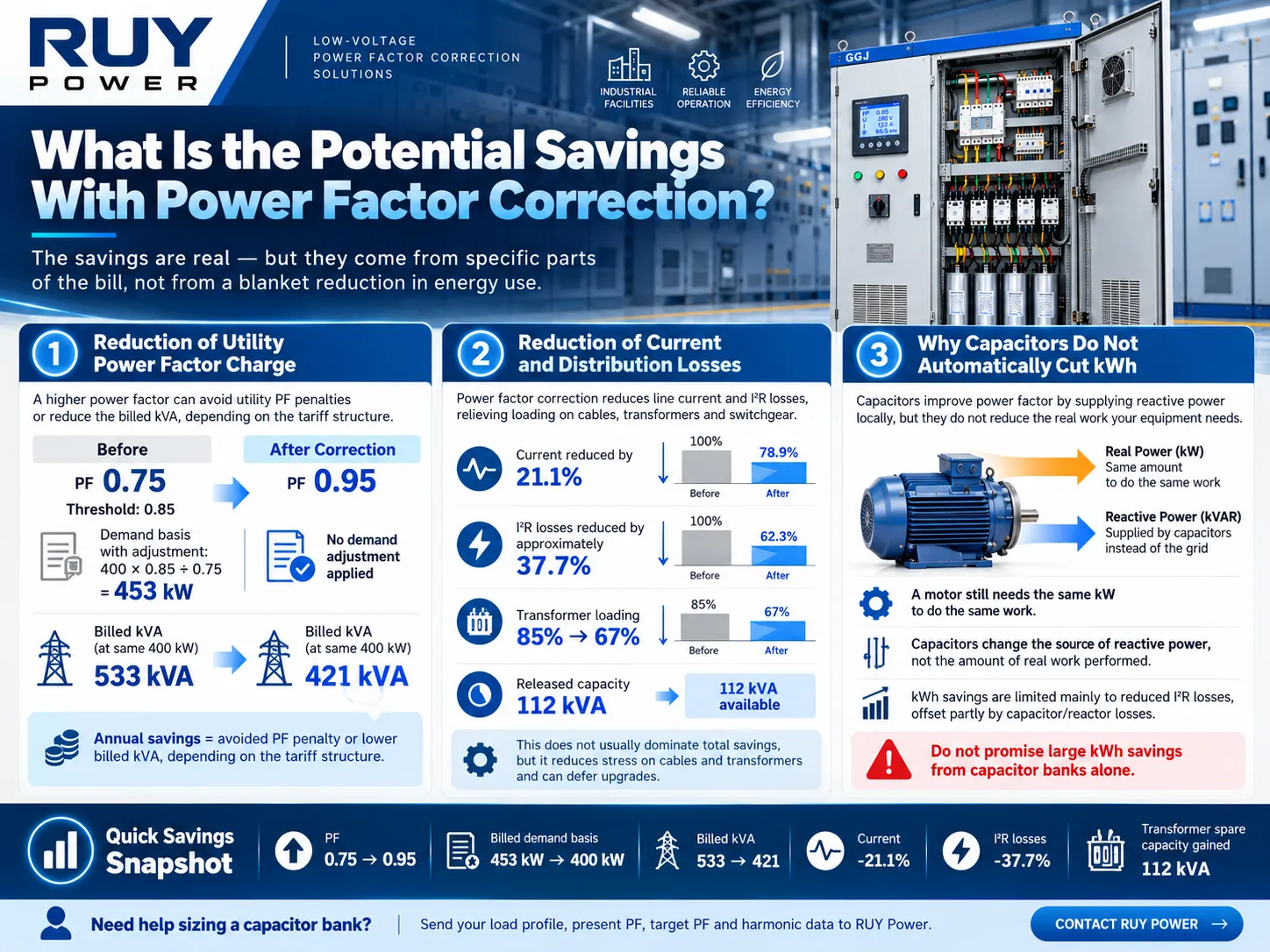
This is usually the most significant saving, and it is easy to make sure that it took place. In the case of demand adjustment tariff with the threshold of 0.85, in our example, the plant is charged based at PF 0.75 on 400 × 0.85 ÷ 0.75 = 453 kW instead of 400 kW. Just use PF=0.95 and there will be no demand adjustment applied. To get the savings, one only needs to multiply 53 by the demand rate and by 12 for the annual figure. In case of kVA rates, the savings will equal drop from 533 kVA to 421 kVA multiplied by the kVA rate.
Reduction of Current and Distribution Losses
The resistive losses are proportional to the square of the current. In this particular case, the current before the capacitor bank decreased by 21.1% and that resulted in the approx.. 37.7% decrease in I²R losses in the cable and in the transformer’s windings. In financial terms, it usually produces small part of the whole energy consumed, because distribution losses are usually low anyhow. More importantly, the loading of the transformer decreases from 85% to 67%, therefore, 112 kVA of capacity is opened up for new load and the transformer or the feeder upgrade can be deferred.
Why the Installation of Capacitors Would Not Lead Automatically to Reduction of kWh
A given motor will need the same kW to rotate the shaft irrespective of the fact that there are capacitors present or not. In other words, the presence of a capacitor does not change the amount of real work done but may change the source of reactive power. In any case, kWh savings limited to the reduction of I²R losses from the point of supply to the bank and vice versa, blocked by capacitors’ and reactors’ losses. Any supplier describing a sizeable cut in kWh resulting from the mere installation of capacitor banks, is in effect misrepresenting the principle of power factor correction.
Five Costly Mistakes When Selecting PFC Capacitors
- 1. Sizing using the transformer load. The approach of “the capacitor kVAR = 30% of the kVA rating” ignores the load. A transformer rated kVA of 1 000 kVA takes a different bank when loaded at 400 kW than 800 kW. Size using kW and kVAR that is recorded.
2. Overlooking harmonics. The practice of sourcing standard capacitors for applications with a third of the load being drives will be a sure way to experience oversized capacitors and fuse failures in less than a year. A Gh/Sn check and resonance estimation must be performed ahead of everything.
3. Targeting unity. Achieving a unity of 1.00 will require more kVAR when compared to a target of 0.95 while putting the facility in a lead mode during low load situations. The target should be set at a range of 0.95-0.98 lagging.
4. Confusing 50 Hz with 60 Hz and nominal vs actual voltage. A 50 Hz capacitor connected to a 60 Hz power supply will draw 20% more current than its nominal. 480 V capacitor on 400 V, however, will deliver about 30% lower kVAR. Such mistakes will happen when the equipment is purchased from a catalogue dealing with sufficient market distance from the subject market.
5. Treating capacitor banks as a “set and forget” solution. Capacitors lose their capacitance over time, contactors wear out, fans and filters get clogged eventually. When the fault is reported by a power factor correction device, the issue will be usually caused by one of the reasons corresponding to such a service failure – the step capacitor doesn’t deliver its kVAR capacity, blown step fuse, unreliable contactor, wrong CT polarity or phase errors, overheating or harmonic overload issue. Check capacitor currents at least once a year and replace the defective device.
Power Factor Correction Capacitor Standards and Safety
Three IEC standards cover a low-voltage power factor correction capacitor bank, each at a different level:
| Standard | What it covers | Why it matters to a buyer |
|---|---|---|
| IEC 60831-1 / -2 | Self-healing shunt power capacitors for AC systems up to and including 1,000 V: ratings, tests, overload limits, discharge devices | Governs the capacitor units themselves |
| IEC 61921 | Low-voltage AC shunt capacitor banks for power factor correction, including built-in switchgear and controlgear; current edition IEC 61921:2017, adopted in Europe as EN IEC 61921:2025 | Governs the complete bank as an assembly |
| IEC 61439-1 / -2 | Low-voltage switchgear and controlgear assemblies: temperature rise, short-circuit withstand, dielectric properties | IEC 61921 refers to it for the enclosure, busbars and wiring |
Capacitor installations in North America must comply with NEC Article 460 and capacitor devices are usually manufactured in line with IEEE Std 18. Establish which listing or certification the installation must comply with from the authority.
Basic safety factors include:
Stored energy. Capacitors hold their charge even after disconnection. According to IEC 60831-1, the discharge must be accomplished to 75 V in no more than 3 minutes, whereas NEC 460.6 requires that 50 V discharge be achieved in no more than 1 minute for 1000 V capacitors, through a permanent or automatic means of discharge. Always allow some time to pass before testing the terminals.
Sizing cables and protection. When determining the conductor sizes and protective devices, take into account capacitive current and harmonics. According to NEC 460.8, the rated current of conductors should not be lower than 135% of capacitor rated current, and IEC practice uses the range of 1.3–1.5 × rated current.
Temperature. It is usually assumed that for every continuous temperature change of 10 °C the capacitors’ lifespan is cut by half. The component should be designed for the expected ventilation and losses during operations of the detuned capacitor bank, not afterwards.
Earthing and casing. Attach the capacitor casing and device casing to protective ground and ensure the level of ingress protectiveness matches the location’s requirements for dust and moisture.
What to Include in a Capacitor Bank RFQ
An exhaustive request for quotation facilitates providers to quote an identical project, thus minimizing exchanges for clarification. It should specify:
Voltage, frequency (either 50Hz or 60Hz) and earthing system (that is TN-S, TN-C, or IT).
Transformer rating, its impedance and secondary voltage; the short circuit level at the bus-bar, if known.
Measured real power at both peak and minimum load, existing PF and desired PF.
Scope of required overall kVAR and method of arrangement, or load profile to be provided in order to let the provider suggest such.
Harmonics data: voltage THD, current THD and 3rd, 5th and 7th harmonic; the list of converters, UPS and rectifiers with their kVA indicated.
Compensation method: either fixed, automatic switch via contractors, thyristor switch, or tuned (either indicate p = 7% or 14% if decided).
Requirements for controller: the amount of outputs, communication (RS-485/Modbus), alarms.
Protection: per step fuses or MCCB, main incoming switch, assembly short circuit rating.
Housing: indoor or outdoor, IP rating, limit of dimensions, cable entry top or bottom, environment temperature and height.
RUY Power GGJ Low-Voltage Capacitor Compensation Cabinet
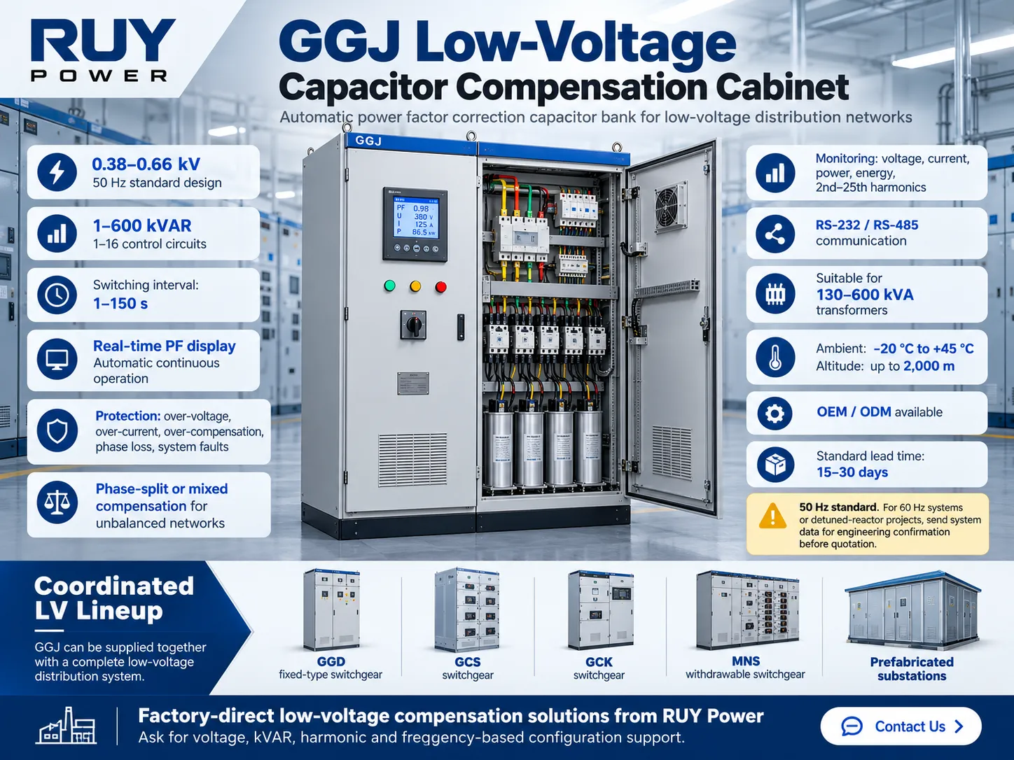
RUY Power manufactures the GGJ low-voltage capacitor compensation cabinet, an automatic power factor correction capacitor bank for low-voltage distribution networks:
- Voltage rating twins 0.38–0.66 kV, which encompasses systems operating at 380 V, 400 V, 415 V, 480 V and 660 V.
Rated frequency 50 Hz or 60 Hz, with capacitors being specified for the chosen frequency.
Compensation power is from 1 to 600 kVAR, with the number of control circuits between 1 and 16.
Switching duration can be adjusted from 1 to 150 seconds; it works automatically and continuously.
Operating voltage range 0.85–1.1 × rated voltage; max-allowed current=1.3 × rated current.
Smart controller allows for power factor demonstration and protects the equipment from over voltage, over current, over compensation and equipment failure; data is saved when there is a loss of electricity.
Compensation can use either phase-splitting method or phase-splitting plus additional systems.
The cabinet allows for monitoring of some parameters of rings, including three-phase voltage and current and parameters of water. - It is appropriate for transformer 130–600 kVA; can install up to altitude 2,000 m and in the environment with temperature between minus 20 °C and plus 45 °C.
Branding and other configurations of the cabinet can be supplied.
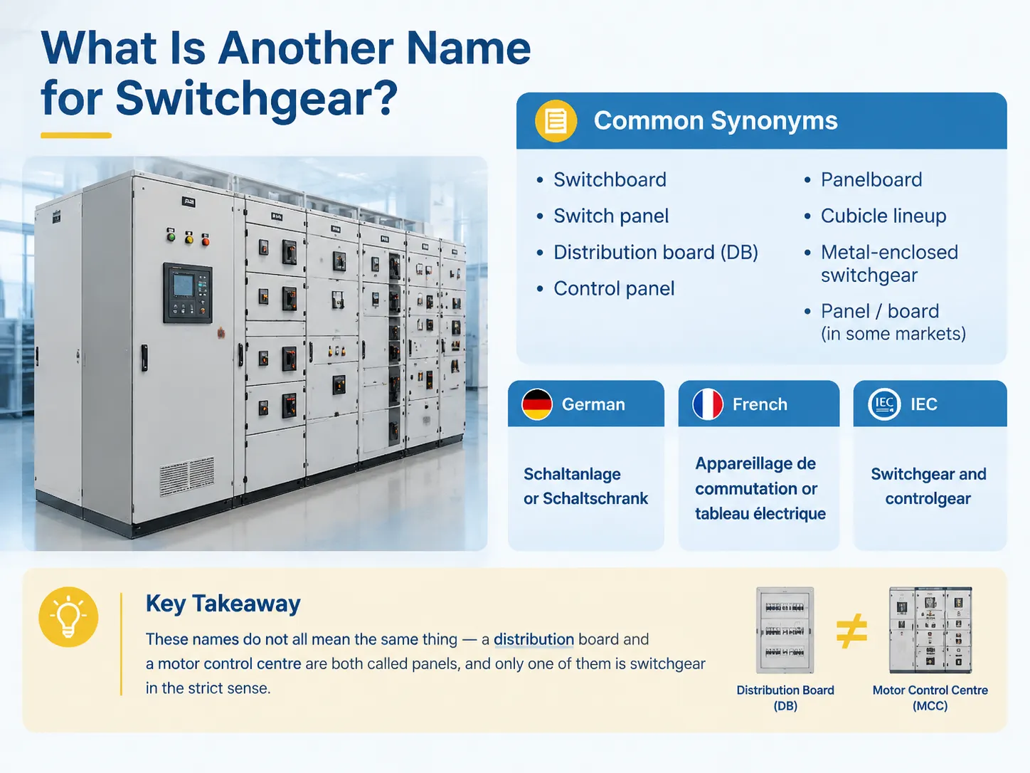
The GGJ cabinet sits in the same low-voltage lineup as RUY’s GGD fixed-type switchgear, GCS, GCK and MNS withdrawable switchgear, so incomer, feeder and compensation sections can be supplied as one coordinated board. For transformer-plus-distribution packages, see RUY’s prefabricated substations. If your documents use different names for these panels, our guide to what else switchgear is called maps the terms by market.
Frequently Asked Questions
What is power factor correction?
What is power factor correction? This technique is defined as supplying reactive power (kVAR) in the vicinity using capacitors. It ensures that inductive loads like motors and transformers do not withdraw reactive power from the utility. Thus, it improves the ratio of real power to apparent power, thus reducing kVA usage, current, and power factor penalties.
How do I know what size power factor correction capacitor I need?
To calculate your kVAR requirements, multiply your actual power in kilowatts by the difference between the tangent of arccosine of PF1 and tangent of arccosine of PF2, or alternatively, make use of the multiplier table and calculator above. Example: A load of 400 kW at a PF of 0.75 is corrected to PF of 0.95 through the use of approximately 221 kVAR. To get the kilowatts and PF, use the data logged at peak and minimum loads, then verify the value of harmonic distortion before making your bank choice.
What is the difference between a power factor correction capacitor and a capacitor bank?
A single power factor correction capacitor is one which is made up of a single component usually rated from 2.5 to 50 kVAR. A power factor correction capacitor bank is one which is constituted of a number of such units along with disconnects, protective gear and busbars. A special case of the power factor corrector is the automatic capacitor bank in which the controller is present which switches steps depending on the load.
How do you measure power factor correction performance?
Contrast the power factor, kVAR, and kVA readings from the main incomer preceding and following commissioning, preferably with a week of logging. Whether the current is measured for each capacitor step is of importance because a step not drawing the expected current has either lost capacitance or experienced a failure in its fuse or contactor.
What does “a power factor correction fault exists” mean?
It is a general alarm from the PFC unit or the BMS, indicating the bank is unable to achieve its target or has identified a faulty condition. Common problems are the broken step fuse, broken contactor, bad capacitor, reversed or incorrectly placed CT, overheating, overvoltage or harmonic overload. First switch off the bank, let the capacitors discharge, and verify the step currents as well as the CT connections before safety reset.
Can power factor correction capacitors reduce my electricity bill?
It is true that low power factor billing charges, when a bill is expressed in kVA instead of kW. Savings arise from eliminating those charges as well as reducing the losses upstream of the bank. Efficient capacitance doesn’t affect the kWh consumption of the devices.
Should I correct power factor to 1.0?
Usually not. A target of 0.95–0.98 lagging captures most of the benefit. Correcting to unity needs much more capacitance and risks a leading power factor and overvoltage when load drops.
Can I use a 50 Hz capacitor bank on a 60 Hz system?
There is a need for a new rating in this case. At the frequency of 60 Hz, the same capacitor provides approximately 20% increased kVAR capacity and current intake and a detuned reactor, designed for the 50 Hz power supply, will be unable to produce the target tunning frequency. It is necessary to order the capacitor bank according to the real frequency and voltage of the system since RUY manufactures GGJ for both 50 Hz and 60 Hz networks.
References
- IEC 61921 — Power capacitors: Low-voltage power factor correction banks. Scope of factory-built LV PFC banks with built-in switchgear and controlgear.
- IEC 60831-1 — Shunt power capacitors of the self-healing type for AC systems up to and including 1,000 V. Capacitor ratings, overload limits and discharge requirements.
- IEC 61439-1 and IEC 61439-2 — Low-voltage switchgear and controlgear assemblies. Assembly-level verification referenced by IEC 61921.
- NFPA 70 — National Electrical Code, Article 460. Capacitor installation, conductor sizing and discharge of stored energy in North America.
- Eaton — Power Factor Correction and Harmonic Resonance: A Volatile Mix. Estimating parallel resonance from short-circuit MVA and capacitor Mvar.
- CIRCUTOR — Capacitor banks with detuned filters in networks affected by harmonics. Choice of 189 Hz and 134 Hz tuning.
- Schneider Electric — Electrical Installation Guide, power factor correction chapter. Gh/Sn selection of standard, heavy-duty and detuned compensation.
- RUY Power — GGJ Low-Voltage Capacitor Compensation Cabinet. Product specifications quoted in this guide.
Need a Power Factor Correction Capacitor Bank for Your Project?
The right power factor correction capacitor bank starts with three numbers — real power, existing power factor and target power factor — and is confirmed by two checks: how much the load varies and how much harmonic distortion the site carries. Send RUY Power your system voltage and frequency (50 Hz or 60 Hz), transformer rating, peak and minimum kW, current and target PF, harmonic measurements and project country, and our engineering team will propose a step arrangement and a GGJ configuration for your site. Contact RUY Power for a quotation.