
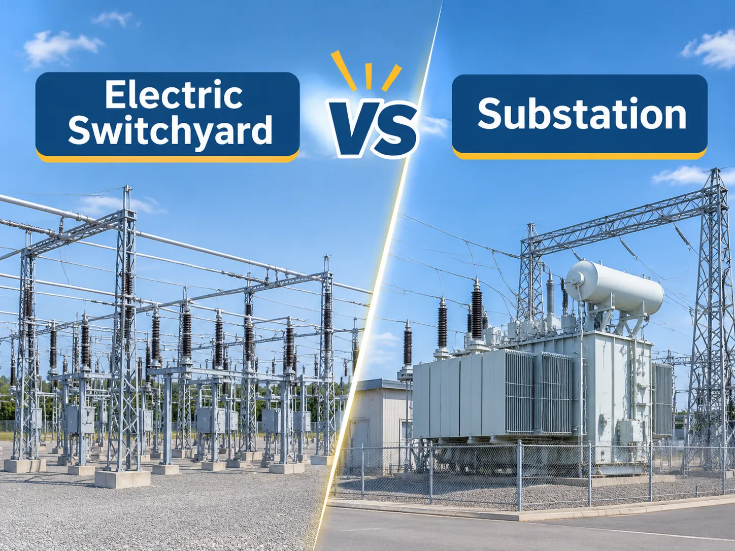
The two words have become synonymous and often interchangeable in all spoken conversations but not in drawings. When electrical energy reaches a substation, the primary task of the equipment there is to step down or up the voltage. On the contrary, a switchyard doesn’t contain transformers and merely re-routes the voltage. Confusion around these two terms isn’t merely a problem of vocabulary mistake but also shows up in one’s technical drawing like scope of works, electrical protection scheme and budget and often surfaces after one has ordered equipment.
Quick answer: To put it simply, an electric switchyard is an above ground assembly of busbars, isolators switches and circuit breakers. A substation contains one or multiple transformers step-up or down the voltage in the course of transmission and/or distribution operations. A switchyard, as a rule occurs next to electrical generators or major substations for network configuration and fault isolation. A substation occurs in case some modification to voltage is required near load centers in the transmission and distribution operation. All the points above characterize a typical type of switchyard.
The following content gives a thorough technical comparison of the two above stated facilities and covers the specifications of each, operational mode of voltages, the ownership, classification and the operation system and how these differences impact the pricing and information regarding layout. The first segment discusses where a switchgear manufacturer fits into the specifications of another party’s project.
The Short Answer: Transformation vs. Switching
Substations exist to effect transformation in the voltage of the power delivered. You cannot deliver power at 138kV or 345kV to a manufacturing facility at that voltage, and it would not be practical to try to transmit 12kV across the country (or even within a state) without consequences. A transformer is the reason a facility exists, and all of the other components of a substation, such as switchgear, protection, and buswork, all support that purpose.
A switchyard is for the purpose of making connections and disconnections of electrical circuits. At a generating facility, the switchyard is used to connect the generator step-up transformers to the outgoing transmission lines and to isolate the circuits without shutting down a plant. At a transmission substation, the switchyard is the high voltage bus section where the transmission lines come into the substation.
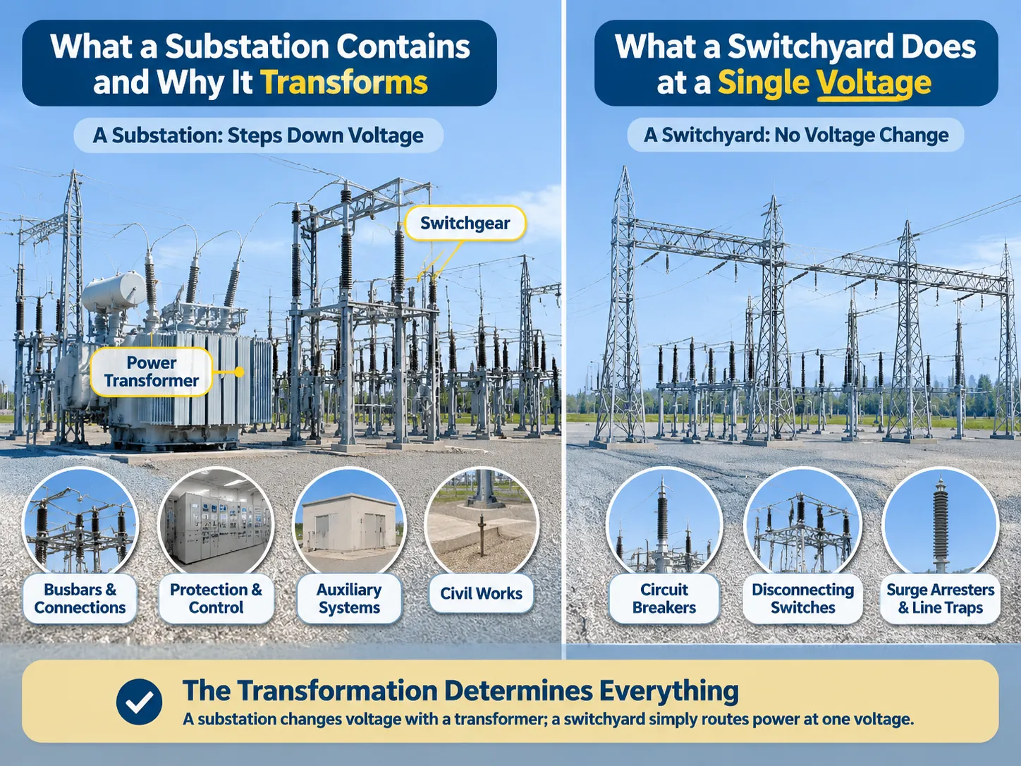
The difference between a switchyard and a substation lies with the fact that a switchyard functions only at one voltage. Therefore, it requires no transformer or tap changer. A substation has at least two voltage levels, hence it requires both. A switchyard exists when a facility has multiple voltage levels and outgoing circuits.
The Contents of a Substation and its Purpose for Transformation
A transmission or distribution substation has six operational groups, each one having to do with transformer operations. One or more, generally with on-load tap changers on the high voltage side to maintain the secondary voltage in range as load changes. An example of this would be a 138 kV/13.8 kV 50 MVA transformer operating between transmission and distribution in North America.
High Voltage Switchgear. All high voltage switchgear including circuit breakers, disconnectors, and earthing switches are present on both sides of the transformer designed in such a way that it is possible to isolate every item for maintenance without turning off any busbars.
Busbar and connections. The rigid or stranded conductors which interconnect the different bays and are rated based on the maximum fault current.
Protection and control. Current and voltage transformers, relay systems, and control room with DC supply, SCADA, and communication devices. The relay protection system provides for the safety of the facility irrespective of the functional safety of the system.
Auxiliary systems. Station service transformer, battery bank, and charger, fire protection systems, and cooling control systems for transformers.
Civil works. Site preparation for analogies such as foundations, cable trenches, oil containment systems, access roads, and earthing grids which is the most underestimated item when considering brownfield developments.
The transformation process is therefore followed by consideration of all primary aspects of the project. The 50MVA transformer operating at 138kV will draw 209A on the primaries with the secondaries drawing 2092A. This means low side busbars and switchgears have to be much bigger than the other side.
What Does A Switchyard Do at a Single Voltage
The list contains a lesser number of equipment items and exhibits a different structural design concept.
Busbars. Only one busbar, double busbar, single busbar plus circuit-breakers and breaker-and-a-half scheme. How the configuration is done affects the amount of the yard that can be kept energized during maintenance.
Circuit-breakers. One circuit-breaker for each circuit in a single busbar configuration plus 2 in breaker-and-a-half arrangement. As the voltage is within the transmission level, the switchgear will be either live tank or dead tank SF6 circuit breaker or GIS equipment.
Disconnectors. Equipment for visual disconnection for maintenance and shall be operated either from the operation room or the computer depending on the voltage levels of energy in the transmission.
Measuring transformers. Current transformers for both protection purpose and metering, voltage transformers for voltage measurement and high voltage for high-voltage electric signals applied to the carriers of information through the carrier.
Insulators and earthing systems. The use of insulators, the earthing systems shall include interlocking devices that cannot be operated unless the circuit is energized.
Geometrical layouts and foundations. The use of lattice steel or tubular steel depending on the wind velocities observed and should take into consideration the electromagnetic fields.
The geometrical layout is based on the electrical distances and not the equipment dimensions. This leads to the fact that although the 345 kV switchyard uses very little equipment, the area occupied becomes large.
Where the Border Lies: Voltage, Configuration and Ownership
There are three tests that can differentiate between the two facilities, and they generally agree with one another.
The test of voltage. If everything functions in the facility at one voltage, then it is a switchyard or switching station; if it is more than one voltage using a transformer between the various voltages, then it is a substation. For example, if a facility has a 345 kV switchyard, two 345/138 kV transformers, and a 138 kV yard, it is a substation with switchyards on either side.
The test of configuration. Switchyards are almost always open, outdoor air-insulated because the voltage is high and current is moderate; air is the cheapest insulation at this point. In contrast, substations can vary. In recent years, however, the trend has been toward indoor, metal-enclosed substations.
The test of ownership. In American, the switchyard at a generator may be owned by the generator itself while the substation (still connected to the distribution system) will be the property of the utility. The difference in ownership determines who will perform maintenance tasks in addition to establishing a contractual agreement that covers maintenance.
The following comparison is between a substation and a switchyard.
| Category | Substation | Switchyard |
|---|---|---|
| Function | Change the voltage, regulate and distribute | Connect, route and isolate |
| Transformers | One or more, including tap changers | None |
| Voltage levels | At least two | One |
| Typical voltage | 69 kV – 765 kV, or 12 kV – 34.5 kV distribution | 115 kV – 765 kV |
| Common location | Near load centers or generation source | Next to the generating plants or major substations |
| Key equipment | Transformers, breakers, busbars, capacitors, protection | Breakers, disconnectors, busbars, CTs and VTs, surge arresters |
| Size determinant | Size of transformation, cooling and oil containment | Insulation clearance and bus arrangement |
| Estimated expenses | $1.5 million – $25 million installed | $3 million – $15 million installed |
The costs are similar because the same civil, steel and protection costs apply to both stations, with the only difference being in transformers since this can constitute around 30-50% of substation equipment costs, along with busbars whose doubling of switchyard costs is attributed to change in configurations from a simple bus to a break-and-half.
Types of Substation and Their Functions
There are two types of substations; thus, each of the classifications appears in specification sheets with no explanation.
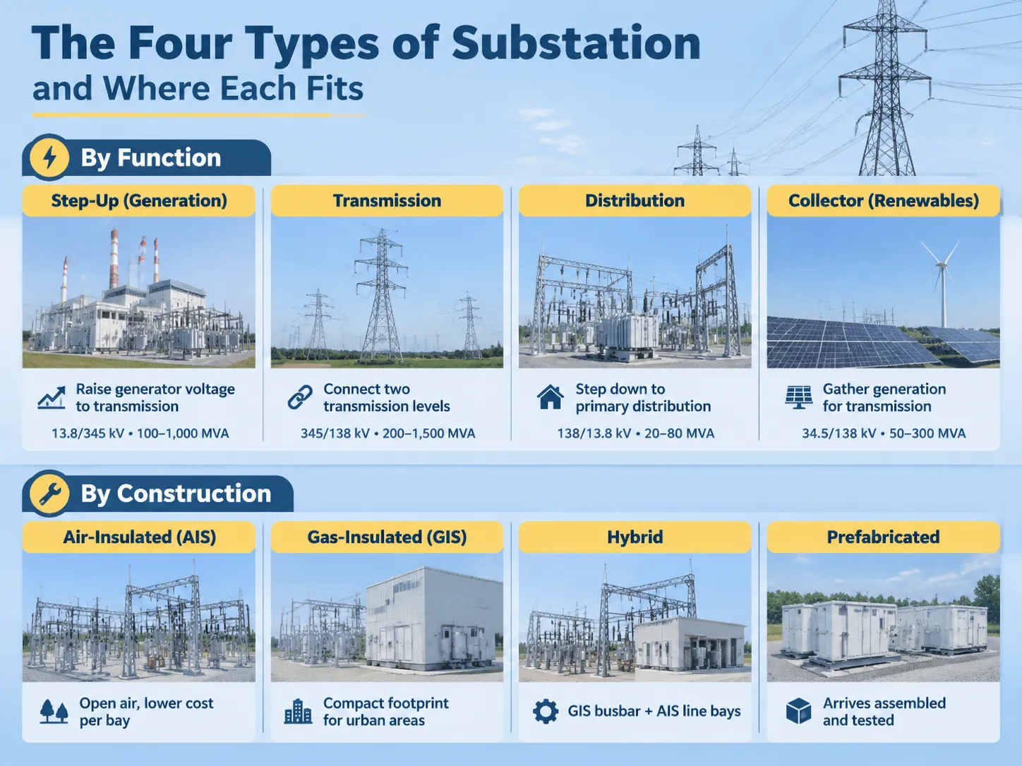
By function. Step-up substation at a generating station increases voltage from generator level to transmission level; the step-down or transmission substation connects between two transmission levels or transmits electricity to distribution networks. The distribution substation decreases voltage to primary distribution levels (primarily around 34.5kV, 25kV, or 12.47kV). The collector substation collects power from several renewable energy stations operating at 34.5kV and hikes it to transmission levels.
By construction. Air-insulated substations (AIS) are the least expensive of all the options for high voltage applications when there is open space available and provide good insulation. Gas-insulated substations (GIS) use the enclosed busbars and breakers in either Sulphur Hexafluoride (SF6) gas or some other alternative gas, and together with other equipment only occupy 10 to 25% of the floor area of an AIS, which makes them very suitable for use in cities and offshore platforms. Hybrid substations combine the two technologies to take advantage of the benefits of both. Prefabricated or skid-mounted substations are delivered to the user pre-assembled and pre-tested, which is why most industrial projects we actually build are typically prefabricated or skid-mounted substations.
| Type | Function | Typical Ratio | Typical Capacity |
|---|---|---|---|
| Step-up (Generation) | Raises the generator voltage to the transmission level | 13.8 – 345kV, 20 – 400kV | 100 – 1,000 MVA |
| Transmission | Connects two transmission voltage levels | 345 – 138kV, 400 – 220kV | 200 – 1,500 MVA |
| Distribution | Steps down the transmission voltage to a primary distribution level | 138 – 13.8kV, 33 – 11kV | 20 – 80 MVA |
| Collector (Renewables) | Collects generation for transmission | 34.5 – 138kV, 33 – 132kV | 50 – 300 MVA |
In regard to the classification of substations, the construction type seems to be more important to the buyer than the functional type, since it determines the footprint, the civil works involved and the time needed for commissioning. Although a GIS design costs more per bay than the AIS substation and uses less land area, the crossover cost point is defined at the price of urban land rather than at any technical limit. Another option that buyers can consider are the prefabricated units which are classified as GIS using the advantages of both technology, but have the drawback that they have to be pre-assembled and tested before being sent out to the user.
Switchgear, Switchyard and Switching Station
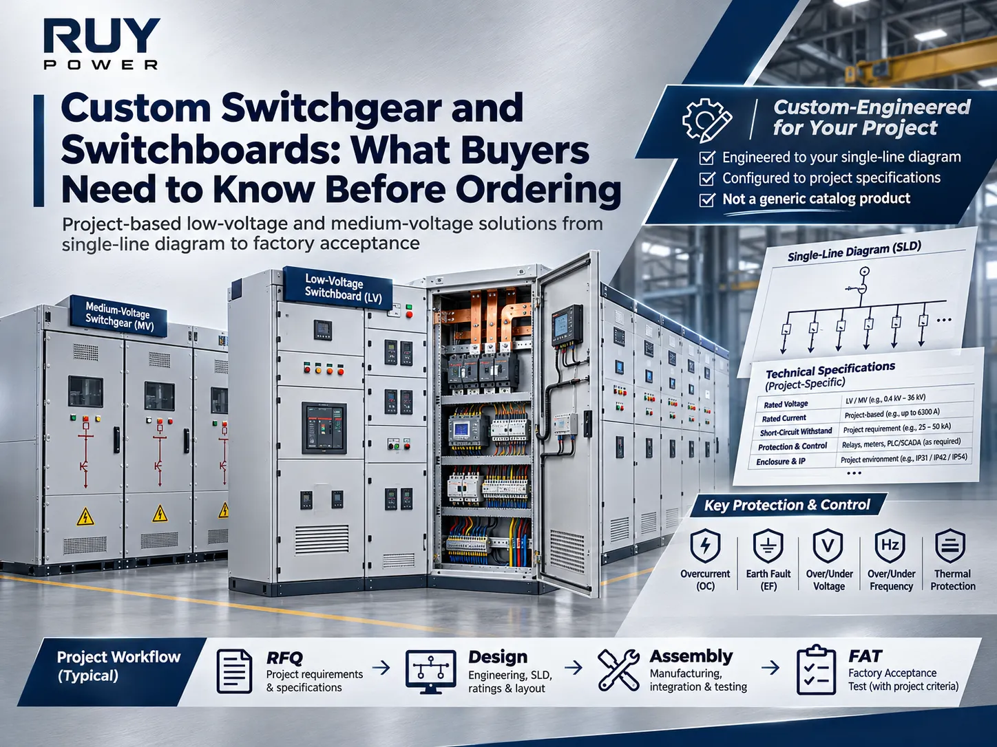
Switchgear, switchyard and switching station are three terms that appears to bear a similarity in term but used to depict different dimensions or sizes of the same concept. Switchgear refers to the entire assembly of switching and protection devices that are usually constructed of metal and permanently packaged in factories as opposed to being built onsite.
For instance, medium voltage switchgear that operates in the range of either 12 kV or 24 kV refers to the assembly of vacuum circuit breakers, current transformers, and electrical relays in cubicles and is considered a product as opposed to a piece of equipment. For example, a 12 kV metal armored switchgear assembly is characterized as withdrawable unit switchgear (reuse of breakers), with separate compartments rated at between 630 and 4,000 amperes with a short circuit withstand rating of between 20 and 50 kA.
A switchyard is an outdoor facility that contains switchgear with air insulation and is specifically used for voltages above 100 kV. Although a switchyard essentially has switchgear, the equipment in it is comprised of open-air equipment, meters instead of guns, and a busbar instead of compartment head.
A switching station is a switchyard located in the transmission system that does not possess any generating or loads.
This has practical ramifications in that a 12 kV project requires the purchase of switchgear, whereas, a 345 kV project requires the construction of a switchyard.
The reason that vacuum circuit breakers have come to dominate medium voltage applications below approximately 40.5 kV is practical in nature rather than theoretical.
Since the arc in a vacuum interrupter is extinguished at current zero due to the rapid dielectric recovery that takes place over its conductive surfaces, there are no gases present that need to be controlled and hence, no arc chute to wear out.
In terms of mechanical life expectancy measured in tens of thousands of operations — without any interruption medium required maintenance — and small form of device that fits into a metal-clad enclosure, a 12 kV VCB rated for 25 kA requires only a fraction of volume taken by oil circuit breaker it replaces in practice.
The insulation level has been specified by IEC 62271-1, which takes into consideration rated voltage according to test requirements defined on different voltage levels — i.e. 75 kV lightning impulse test for a 12 kV device, 125 kV lighting impulse test for a 24 kV one, etc.
At higher voltages above 40.5 kV, SF6 circuit breakers will be generally employed instead of vacuum breakers due to SF6 gas having possibility of usage only. Because global warming potential of SF6 is about 23,500 times that of CO2, it is not surprising that every utility company complying with F-gas obligations tends to choose vacuum technology instead of SF6 as the medium.
The protection scheme is determined by the choice of circuit breaker type. For example, at 12 kV, a vacuum circuit breaker will be protected by means of numerical relay with overcurrent and earth-fault elements showing signals from current transformers located in the cubicle.
The duplicate system for transmitting power at 345 kV can be a serious problem as it carries an error if the trip mechanism fails.
Outdoor Layout, Clearance, and Price
The layout of the buildings is the biggest differentiator with these two structures, and people use technical specifications in creating either facility much cheaper or much more expensive than necessary in both cases.
In a switchyard, the busbars dictate the building. The use of a ground bus proves cheaper but prevents any maintenance work from being performed without losing the service entirely. On the other hand, having a double busbar allows one bus to be inactive while the other is in operation. A ring bus will provide good reliability with the use of fewer breakers; whereas a breaker-and-a-half design will give a higher reliability rate but it will cost approximately 1.5 times that of the single busbar system since it uses 1.5 breakers for each circuit instead of one.
When talking about a substation, the layout refers to the transformer along with the method of cooling used. An oil-immersed transformer with a 50 MVA rating requires oil containment, fire walls, and distance between buildings constructed around the transformer. Therefore, in many instances due to all of those requirements, the electrical layout becomes secondary to the selected location of the electrical equipment. However, in the case of using a dry-type transformer, it would eliminate oil containment, though it is seldom used at voltage levels higher than 34.5 kV.
The other thing that people forget about is the cost of doing civil work. For example, a grounding grid for a 138 kV station may require thousands of kilometers of cabling and conductors, and such civil work costs more when it comes to retrofitting existing facilities because the existing grounding system will need to be modified and retested for verification after the installation is done.
The applications of high voltage switchgear we have supplied provide the trends in terms of projects, specifically on the number of bays and the layout of switchgear for each application.
Making the Engineering Work
When making a choice between a substation and switching station, the network usually makes the decision, whether or not they want to. If voltage transformation is necessary, the transformer will dictate this. The owner will control the arrangement, the design of the project, and the method of procurement of equipment.
This means that there are three factors that play a part in determining the outcome. Electrical factors depend on the busbar type which determines reliability and the number of breaker. The method of construction dictates the space taken by construction and civil work. If GSIS type of switchgear is used, it exchanges more space for lower cost of equipment. Finally, the equipment will determine the delivery timing of ordered material especially at present time since transformer delivery will take from 36 to 48 months as a minimum for big size equipment from Western suppliers.
For the medium voltage projects things are completely different and done at a higher speed. The same substation with 12 kV or 24 kV built from metal clad switchgear with a distribution transformer will be constructed in 6 months or less. The same is applicable even up to the 40.5 kV where armored withdrawable switchgear is used. This is why factory companies have the actual competitive field because it is most of the industrial and commercial structures being constructed.
Where RUY fits
At RUY, we specialize in making the medium voltage equipment within a substation rather than the substation itself. Our products include metal-clad and metal-enclosed switchgear at both 12 kV and 40.5 kV, ring main units, and prefabricated substations, just to name a few. The majority of our work serves industrial plants, commercial buildings, and distribution networks where only standard assemblies conforming to the single line diagram are required.
The 40.5 kV armored withdrawable switchgear ranks highest of all 40.5 kV switchgear in regards to short circuit withstand ratings between 1,250 and 4,000 A and short circuit withstands of 31.5 kA which meet IEC 62271-200 standards. On the other end of the spectrum, the ring main units together with prefabricated substations serve the distribution sectors where footprint takes precedence over high short circuit ratings.
We do not produce switchyards at RUY. Switchyards used with equipment rated at 40.5 kV and higher fall within a different equipment classification with a separate series of functionality tests. Thus, it is much easier to express the difference early rather than waiting for it to show during the design analysis process.
FAQ
What is a switchyard in a substation?
The switchyard represents the portion of a substation (or the facility that is adjacent to it) where busbars (as well circuit breakers and disconnecting switches) connect incoming and outgoing circuits. It encompasses no transformer, and none of the voltage is converted. In the case of a transmission substation, the switchyard is located on the high voltage side just before the transformers arrive, while in the case of a generating facility, it represents the switchyard just before the generator step-up transformer to the outgoing lines.
How does a switchyard differ from a switchgear?
Size and construction: the switchgear represents piece of equipment created by the factory that includes circuit breakers, disconnectors, and safeguarding devices in metallic casings (that generally operate at medium voltage). In contrast, the switchyard represents an outdoor equipment that employs open busbars as well as structures above the ground and operates at transmission voltage. While a 12 kV system may purchase the switchgear, a 345 kV system will purchase the switchyard.
What are the four categories of substations?
According its function, substations operate at four different levels: generating plants raise voltage, substations transfer voltage from one transmission level to another, primary distribution substations reduce voltage levels for major distribution systems, and collection substations gather energy from renewable energy sources.
Depending on their design, four categories of substations exist: air-insulated, gas-insulated, hybrid, and prefabricated. Both methods appear in specifications, with the design often dominating the buyer’s option based on the importance of space, civil works, and time frame for the completion of the commissioning process.
Why use VCB in substations?
The vacuum interruption has a long lifecycle because there is no need to maintain the interrupting medium, and the unit’s small size permits the use of a metal enclosed cubicle. There are thousands of operations at 12 kV to 40.5 kV, as no maintenance of interruptions is required, and that is why it has replaced other technologies (which operate at higher operating voltages). As voltage levels increase above 40.5 kV, SF6 becomes commonplace.
References
- Hitachi Energy — Substations and Switchgear Technologies
- Siemens Energy — Grid Technologies and Switchgear
- General Electric Vernova — Grid Solutions and Equipment for High Voltage
- LandGate — Grid Stations, Substations and Switchyards Explained
- NEMA — Standards for Switchgear and Equipment of Substations
Conclusion
One key difference between the switchyard and the substation lies in the transformer: the transformer in the case of the substation performs the task of changing the voltage in terms of its orderly use. Therefore, all further aspects (the number of voltage levels, clearance for footprint, and protection scheme) depend on this single aspect. When making purchases, customers should not concern themselves with the titles of either facility but focus instead on what they require for their specific project. If a transformer is needed for conversion of the voltage, the project qualifies for establishment of a substation. The diagram may significantly reduce costs when created.