
It can be concluded that the location of occurrence of switchgear failure will always be the same, or, simply put, it will always be Tuesday afternoon in July regardless of any plans for that date. It also cannot be ruled out that the cause of this failure is something simple, which could have been discovered within twenty minutes during a power outage on Saturday. Something like a loose bus joint in a temperature of 38 degrees, or a circuit breaker that has never responded in the last three years; or even a heating circuit that failed two winters ago, meaning that the secondary terminals of CT could experience a humid atmosphere.
For several decades, maintenance has also become less complicated, being reduced to technical problems with different criteria used to evaluate the effectiveness of the maintenance operations and a protocol containing all expectations and recorded test results.
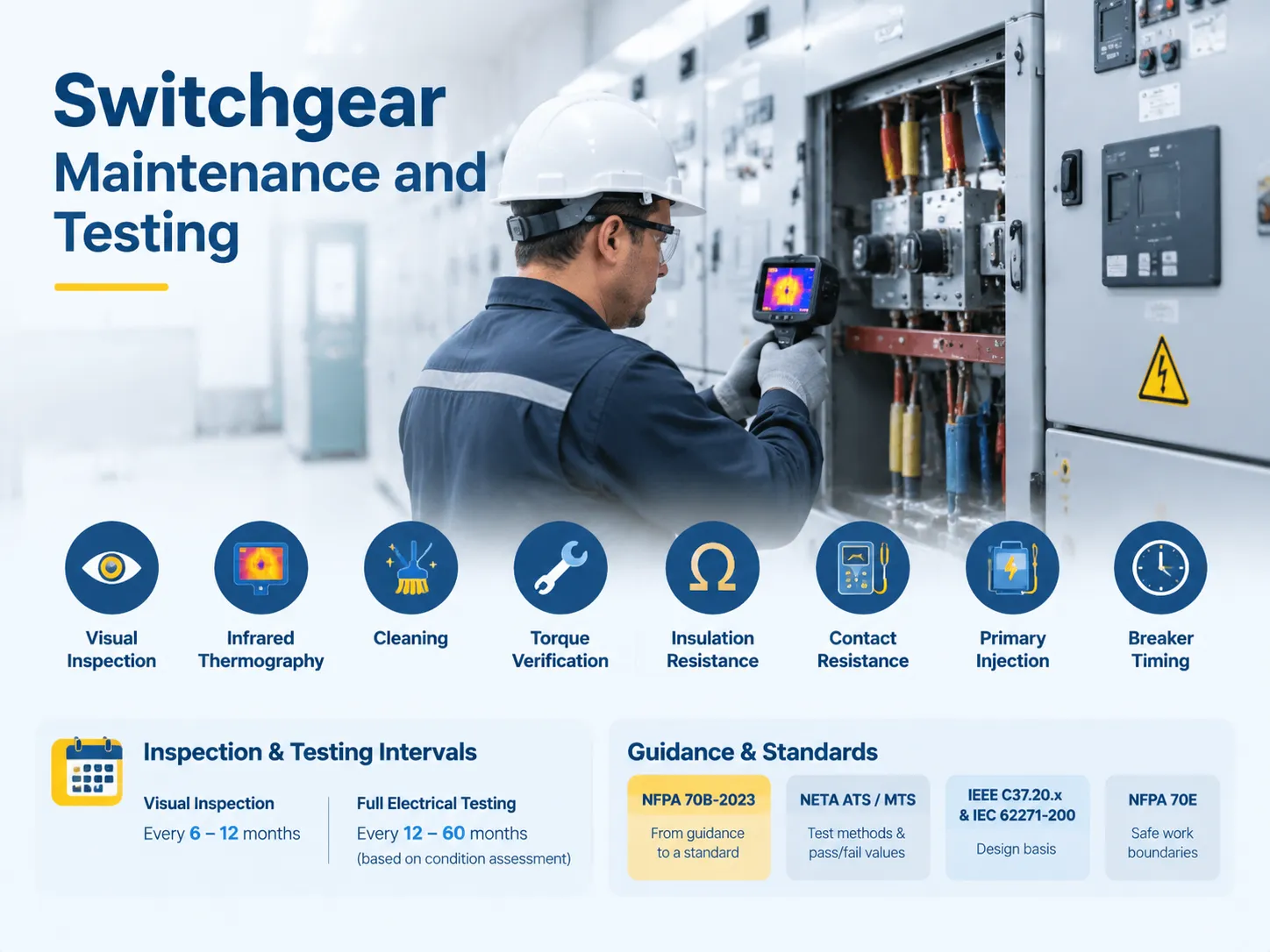
Switchgear maintenance involves several procedures such as routine visual inspection, thermal imaging and cleaning, torque check, insulation test, load checks and time setting of modes. According to NFPA 70B-2023, the maintenance of switchgear must be performed every six to twelve months for visual inspections, whereas the period for full inspection of switchgear is between twelve to sixty months depending on the condition of the switchgear. NFPA 70E provides limits to be followed when performing maintenance work, while NETA ATS and MTS provide instructions for performing tests and specify criteria for passing or failing tests. The design principles for manufacture of switchgear are indicated in IEEE C37.20.x and IEC 62271-200.
Why This Became a Compliance Item
The NFPA 70B has existed for many years as a guidance document. The 2023 edition has re-grafted it into a standard, and its wording has shifted from stating that the owner “should” carry out maintenance to asserting that the owner “shall” maintain the electrical maintenance program. This is a significant change since this is the term that matters to the insurance companies, auditors, and authorities having jurisdiction.
Three provisions carry most of the implementation burden. Chapter 4 tells what the program must include, down to allegations regarding record retention and the process of the actual implementation. Chapter 8 gathers together all the field testing procedures and their acceptance criteria that have been dispersed in the previous editions. Finally, Chapter 9 ties the intervals to the assessment of the condition of the equipment instead of using a general schedule.
The assessment itself is quite simple. Each piece of equipment is assessed along three parameters: state of operations, significance of equipment, and environment of operation. The worst scored parameter determines the interval. For example, it doesn’t matter if a piece of equipment operates properly and is non-critical if it is situated in a foggy damp room.
The most problematic situations are created by high voltages. A project to install a 33 kV transformer into some rural areas might cope with extremely low loads during its whole life cycle, but it has to live in a hot and humid environment, which is worse than anything else.Treating it on the same calendar as an air-conditioned 480 V switchroom is how you end up with a failed cable termination in August, which is exactly the pattern described in these high-voltage switchgear application cases.
What a Defensible Programme Contains
Each of the six components is crucial for the stability of the other five.
- An inventory of vital importance. Every cubicle, every breaker, and every transformer has to be measured in regard to its technical age and failures. Otherwise, the inventory would be meaningless.
- There should be written procedures for each piece of equipment. It is not enough to have the instruction manual in place; it is necessary to develop a workable procedure where the whole testing process is described, including tests order, testing voltages, and acceptable test result values.
- There should be a schedule that works in real life. It is frequent for companies to change their plans, and if the maintenance takes 12 hours according to the schedule, and the 12 hours window will be lost several times in a row, then the program has stopped, and the machines continue to age without informative monitoring.
- Record keeping. It is not enough to indicate whether the test failed or not. There is a huge difference between an insulation resistance of 1.2 GΩ, and the same insulation resistance a year after commissioning which is measured at 8 GΩ.
- The system of corrective action needs to be in place. It is not enough to perform a proper inspection. The most frequent finding after an audit is not a missing test, but a test during which a hot joint was indicated, but it was never repaired by anybody.
- There should be a sufficient staff. There is no coincidence that the NETA certification exists, as it is impossible to interpret a time trace or a partial discharge signature without practical training. Manufacturers who supply the equipment can support this layer without owning the whole programme, which is the boundary RUY Power works within: equipment and its factory test data, plus technical service on the supplied lineups, rather than a site maintenance contract.
Intervals: The Condition Assessment Drives Everything
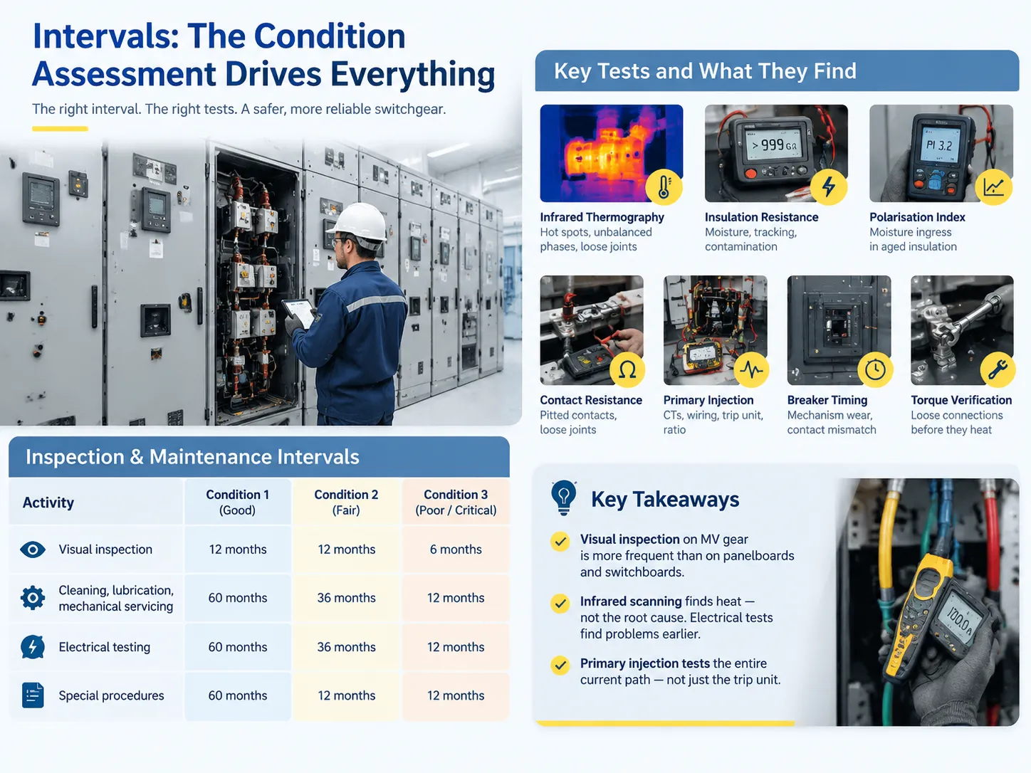
The table below summarizes the NFPA 70B Chapter 9 intervals for switchgear. Condition 1 indicates good condition, Condition 2 indicates fair condition, and Condition 3 refers to poor or critical condition; the most unfavourable of all the evaluation data has to be considered.
| Activity | Condition 1 | Condition 2 | Condition 3 |
|---|---|---|---|
| Visual inspection | 12 months | 12 months | 6 months |
| Cleaning, lubrication, mechanical servicing | 60 months | 36 months | 12 months |
| Electrical testing | 60 months | 36 months | 12 months |
| Special procedures | 60 months | 12 months | 12 months |
To begin with, it is important to have two practical points in mind. When it comes to visual inspections, switchgear is checked out at a significantly shorter interval compared to the panelboards and switchboards, which have a visual check done every 60/36/12 months. This means that while performing an open-door check on the MV switch gear, a lot more failure spots are present. Also, just to remind, infrared scanning cannot replace electrical testing because it is only able to detect the heat – this implies that it only sees the problems which have already occurred.
Under normal circumstances, the system owners end up having a three-year de-energized cycle, as well as an annual energized cycle in this case, and this can be called a reasonable interpretation of Condition 2.
The Tests, and What Each One Finds
| Test | Method | What it detects | Typical acceptance |
|---|---|---|---|
| Infrared thermography | Loaded scan, doors open, ≥40% load | Loose joints, unbalanced phases, failing lugs | ΔT under 15 °C between phases |
| Insulation resistance | 1000 V DC for 600 V class, 2500–5000 V DC for MV | Moisture, tracking, contaminated insulators | 1 GΩ at 1000 V; trend matters more |
| Polarisation index | 10-minute / 1-minute ratio | Moisture ingress in aged insulation | ≥2.0 |
| Contact resistance | Micro-ohmmeter, 100 A DC, four-wire | Pitted contacts, loose bus joints | Within 50% of the lowest pole |
| Primary injection | Current injected through the primary circuit | Trip unit calibration, CT ratio, wiring errors | Within the published TCC band |
| Secondary injection | Signal into the trip unit or relay test terminals | Protection settings, logic, timing | Matches coordination study |
| Breaker timing | Travel analyser, close and open | Slow mechanisms, contact mismatch, dashpot wear | Per manufacturer, pole to pole within 2–3 ms |
| Torque verification | Calibrated wrench on every bolted joint | The loose connection that has not heated yet | Manufacturer value or NETA Table 100.12 |
Insulation resistance is the test that people usually misunderstand. According to NETA Table 100.1, the minimum acceptable insulation resistance is 25 MΩ at 250 V DC and then it goes up to 5 GΩ at 5000 V DC. But these are simply minimum values that must be met; they are not goals. Good insulation in medium voltage bus system would indicate hundreds of gigohms of resistance. Passing the minimum requirement for insulation resistance in a new installation causes deeper investigation, not just signing the report.
Primary injection is the only test to prove the entire current path. Primary injection is the only way to check the whole system components too keeping in mind that secondary injection tests only the trip unit. Primary injection tests all components, since actual current flows through the test circuit.Testing the KYN28-12 armoured withdrawable switchgear without primary injection leaves the CT secondary circuit unverified, which is where a surprising number of misoperations originate.
What the Results Actually Tell You
Thermography is regarded as the most effective test in terms of results per time spent, but the scan should be done under load. Imaging the bus while not loaded will yield no results because there is simply nothing to image since there is no heat. The usual practice says that there should be at least 40% of the rated current during scanning, and thus a case when the scan is performed under 15% load should be considered inconclusive.
It is necessary to read deltas instead of absolute temperatures. For instance, a joint at 62°C in a room at 40°C is 22°C higher than the ambient temperature and requires action. The same joint at 62°C in a room of 55°C is only 7°C above the ambient temperature, which is a perfectly acceptable temperature for the load. The common severity bands provide that the temperature rise of 1–3°C is an indication of a possibly defective item, 4–15°C indicates probable issues, and over 15°C means the item should be repaired before the power is restored.
The same principle is applied to contact resistance. Readings of each pole need to be compared against the readings taken from the other poles from the same breaker and compared against the same breaker readings taken a year before. Reading of one pole that is 50% higher than the lowest reading is a finding, while the reading of all three poles that are 40% higher than the previous year’s readings is a different point altogether (indicating possibly faulty measuring setup or contacts wearing together).
Timing traces provide the most amount of information but very few people read them. In addition to passing or failing against the manufacturer’s limit, one should compare the values in the pole to pole manner and the shape of the open trace. For example, if the mechanism has been 4ms slower than a year before in every cycle, it may indicate problems with lubrication long before any failures.

Common Findings, and What They Cost
Four findings account for most of the repair budget in a mature program.
- Loose bus joints. Most times it was a torque problem due to never being re-torqued or improper installation. At the delta of 8 degrees Celsius, it is a re-torque and return visit; at a delta of 60 degrees Celsius, it is a replacement of the bus section or worse. This alone is worth an annual scan.
- Dead space heaters. Condensation in an MV cubicle destroys insulation and creates tracking across barriers. Space heaters run continuously in most designs; a failed heater is invisible until the insulation resistance test comes back low in the rainy season.
- Seized racking mechanisms. A drawout breaker that has not been racked in five years will not rack when you need it, and forcing it would damage the shutters and the secondary disconnect block. Exercising when connected, tested, and disconnected involves annual mechanical checks.
- Relay settings that no longer match the study. Coordination studies change when a load is added or when a utility transformer is changed. The field relay will not automatically update itself. Re-verifying settings against the current study takes about 20 minutes per relay and is routinely skipped.
Safe Work: The Part That Gets Skipped
Most of the work performed in switchgear maintenance is usually carried out de-energised but being de-energised is not sufficient to consider it safe work. To lock and tag out a system under OSHA 1910.333, you must ensure that all conductors have reached zero-energy state, confirmed by the use of a tested instrument used on a known live source before and after the procedure. The procedure does not only require just to have a glance at the light indicator, but instead requires having three-point confirmation.
The remaining part is covered by NFPA 70E: it includes arc flash risk assessment, incident energy label, PPE category of a particular operation, as well as boundary distances. However, two important things that confuse people about 70E should be taken into account. First of all, the provided label will only be valid for the equipment configuration for which it was calculated, which means that changing the transformer or adjusting the utility fault level will invalidate it. Additionally, switching the breaker remotely cannot be considered the same as doing it locally, meaning that the PPE requirements in these two cases will differ.
As for energised work carried out in switchgear, it is limited to diagnostics that cannot be carried out safely when the equipment is de-energised, which usually means thermography and sometimes partial discharge measurements, therefore both types of work require proper risk assessments and PPE.
Repair, Retrofit or Replace
Normally, the choice boils down to three numbers: the age of the line-up; availability of spare circuit breakers and the fault current level on the busbar as compared to the circuit breaker rating.
If we take a 25-year old low voltage line-up whose insulation condition is satisfactory and spares are available, it would be worth modernizing it. We can provide it with new circuit breakers, current transformers and meters, but keep its shell. If the circuit breaker has a short-circuit current rating below the calculated fault current, then there is a problem requiring engineering efforts that is beyond maintenance capabilities. Additionally, no testing will be able to fix a busbar that is not able to carry a current.
The retrofit option is a compromise solution, but this is where the requirements are very important. Process of switching from analogue protection to digital relays in the existing switchgear involves the use of correctly rated current transformers, reliable auxiliary supply and accurate wiring documentation. An OEM that builds the custom and OEM switchgear assemblies for a project usually has better access to the original drawings than a third-party retrofit contractor does, which shortens the survey phase considerably.
Low-Voltage Lineups Are Not Small Medium-Voltage Lineups
The tests interfere with one another but not the failures.
In low voltage (LV) switchgear systems, the main place of failure occurs in the drawout connections, as there is a high current flowing through them. The connection is also made by hand. Furthermore, it is more likely that contact resistance and torque checking are more important than insulation resistance, which passes for the dry boards at voltage rates of almost 480 volts. The annual infrared scans take care of everything else.
The insulation and partial currents prevail in medium voltage (MV) equipment. Even if the insulation resistance test of a cubicle rated at 12 kV is passed at 5 GΩ, the failure may be in the process of tracking because the test voltage does not put the surface under stress like the actual working voltage.This is the practical difference between an MNS low-voltage withdrawable assembly and a metal-clad MV lineup, and it is why the two should never share a single maintenance procedure with the voltage level edited out.
The switchgear that works at a voltage level of above 52 kV and higher is beyond what the most of the industrial-related programs can handle. Moreover, RUY Power products do not cover this range. Such installations represent transmission facilities, which means there is a separate system of operation and maintenance for them, as well as separate contractors.
FAQ
How often should switchgear maintenance be done?
According to NFPA 70B-2023, visual inspection of switchgear happens every 6 to 12 months, while cleaning, mechanical servicing and electrical testing happen every 12, 36 or 60 months, depending on the equipment condition assessment. However in practice, most industrial sites prefer an annual energised routine inspection with infrared scanning and a de-energised full test at intervals of 3 years adjusting to annual testing for critical or ageing equipment.
How do you test switchgear?
Turn off the energy supply and lock it out, and follow through the steps of the maintenance operation; start with visual inspection and equipment checks, and continue with cleaning of equipment, verification of all bolts and nuts for proper torque, measuring of insulation resistance, obtaining the polarisation index on MV insulation, checking contact resistance of poles by means of a 100A DC current which reflects the norm for the component tested. Continue with primary injection that verifies the capacity of the trip unit and the current converter circuit, then discuss the secondary injection and the settings of the relay. Finish the task of measuring the circuit breaker time through using a travel analyser and finally perform the test of interlocks, values of the indicator or control and record.
What are the 7 types of maintenance?
There are seven types of maintenance that are usually described. The seven types are: preventive (calendar or running time based), predictive (use of condition data to predict failure), condition-based (maintenance is done when some value changes), corrective (the detected fault is repaired), reactive (maintenance is performed after the equipment has malfunctioned), reliability-centred (maintenance is done depending on the importance of the expected failure), and predetermined (scheduled maintenance in specific time periods regardless). In general, switchgear programmes employ preventive, predictive and condition based maintenance, while the last group is mainly used for non-critical spare parts.
What are the testing standards for switchgear?
Test standards in North America are defined by ANSI/NETA ATS for tests to confirm acceptance and ANSI/NETA MTS for tests to confirm maintenance, while acceptance tests are described by NETA ECS. Specifications for the design and testing of equipment comply with all IEEE C37.20.1: low-voltage metal-enclosed switchgear; C37.20.2 for metal-clad MV; C37.20.3 for MV breaker switchgear; C37.06 for rated performance; C37.09 for testing. On a global level, the corresponding standards are IEC 62271-200 for MV metal-enclosed switchgear, IEC 62271-1 for basic specifications and IEC 61439-1 and 61439-2 for low-voltage switchgear.
References
- NFPA 70B — Standard for Electrical Equipment Maintenance, 2023
- NFPA 70E — Standard for Electrical Safety in the Workplace
- InterNational Electrical Testing Association — ATS and MTS Specifications
- 29 CFR 1910.333 — Selection and Use of Work Practices
- UL Solutions — Switchgear and Assemblies Certification
Conclusion
The program, intended for maintaining switchgear in a working condition, has been purposely designed so that the process is rather boring. The process consists of performing a yearly monitoring process, tightening bolts that look to be good based on the results of the monitoring, and testing insulation and trip units every third year with the data recorded in order to speak about trends in the future rather than particular situations at that moment.
Predicting lineup failures is rarely connected to poor design, but comes from such things as not changing a heating element, not moving a switch, as well as a temperature difference that was equal to eight degrees three years ago and is equal to forty-seven degrees now.