

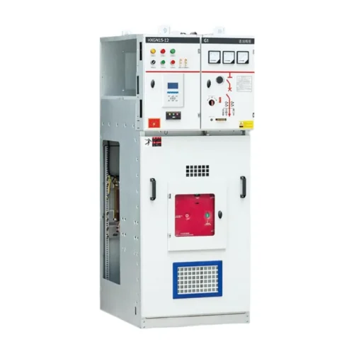
Overview
The HXGN15-12(Z) AC metal-enclosed switchgear (hereinafter referred to as “switchgear”) produced by RUY Power is suitable for rated voltage 3.6~12kV, 50Hz, rated current 630A~3150A three-phase AC single busbar and double busbar, single busbar with bypass system. As power receiving and distribution, it can meet the needs of various types of power plants, substations (stations) and industrial and mining enterprises.
This product complies with national standards GB3906 (3-35kV AC metal-enclosed switchgear), IEC60298 “AC metal-enclosed switchgear and control equipment”, and DL/T402, DL/T404 standards, achieving the “five preventions” functional requirements.
Normal Operating Environment
1. Ambient air temperature: -15℃ ~ +40℃;
2. Altitude: 1000m and below;
3. Humidity: daily average not greater than 95%, water vapor pressure daily average value not exceeding 2.2kPa; monthly average value not greater than 90%, water vapor pressure monthly average value not exceeding 1.8kPa;
4. Earthquake intensity: not exceeding 8 degrees;
5. Places free from fire, explosion hazards, chemically corrosive gases and violent vibration.
Note: Special requirements can be resolved through negotiation with RUY Power.
Functions and Features
The HXGN15-12(Z) switchgear is a metal-enclosed box-type structure. The cabinet frame is welded from angle steel. The cabinet is divided into circuit breaker chamber, busbar chamber, cable chamber and instrument chamber, etc., separated from each other by partitions.
The circuit breaker is located in the lower part of the cabinet body. The rotation of the circuit breaker is connected with the operating mechanism by a pull rod. The upper terminal of the circuit breaker is connected with the upper isolating switch, and the lower terminal of the circuit breaker is connected with the lower isolating switch and the lower outgoing cable connection terminal. A pressure release channel is also provided between the compartments. When internal arc short circuit occurs, gas can release pressure through the exhaust channel. To control equipment and DL/T402, DL/T404 standards, achieving the “five preventions” interlock.
The busbar chamber is located at the upper part of the cabinet body. In order to reduce the cabinet height, the busbars are arranged in product characters, supported by 7350N bending strength ceramic insulators, and the busbar is connected with the upper isolating switch terminal, which is also the compartment between the cabinet and the cabinet.
The cable chamber is located in the lower part of the cabinet body. Voltage display devices can be provided on the supporting insulators in the circuit breaker chamber, and the wires are fixed on the bracket. For the main connection or linking scheme, this chamber is the linking cable chamber. The relay chamber is located in the upper front part of the cabinet body. Various relays can be installed on the mounting plate in the chamber, and supporting brackets are provided in the chamber. Indicators and components such as signal elements can be installed on the door, and a second small busbar can also be laid on the top.
The operating mechanism of the circuit breaker is installed at the left front position, and the operating and interlocking mechanisms of the isolating switch are above it. The switch cabinet is double-sided maintenance. The secondary components in the relay chamber are maintained in front, the mechanism linkage and transmission parts are maintained in front, and the main wires and cable terminals are maintained behind. A lighting lamp is installed in the circuit breaker chamber. A national standard socket is provided below the door, with parallel grounding busbar, specifications: 3×30mm.
Mechanical interlock: in order to prevent live separation and closing of the isolating switch, prevent mis-opening and closing of the circuit breaker, prevent live closing of the grounding switch; prevent live closing of the earth switch; prevent mistakenly entering the live compartment when the earth switch is in the closing position, the switch cabinet has corresponding reliable mechanical interlocks to ensure operational safety. For product dimensions and detailed structure (see Figure 1, Figure 2, and Figure 3).
Main Technical Parameters
| No. | Name | Unit | Value |
|---|---|---|---|
| 1 | Rated voltage | kV | 3.6、7.2、12 |
| 2 | Rated current | A | 630~3150 |
| 3 | Rated short-circuit breaking current | kA | 20、25、31.5、40 |
| 4 | Rated short-circuit making current (peak value) | kA | 50、63、80、100 |
| 5 | Rated dynamic stable current | kA | 50、63、80、100 |
| 6 | Rated short-time withstand current | kA | 20、25、31.5、40 |
| 7 | 1min power frequency withstand voltage (between phases, phase to earth) | kV | 24、32、42 |
| Lightning impulse withstand voltage (across the fracture) | kV | 40、60、75 | |
| (across the fracture) | kV | 46、70、85 | |
| 8 | Protection grade | IP2X | |
| 9 | Main wiring form | Single busbar section and single busbar with bypass | |
| 10 | Cabinet operation mode | Cable entry/exit, wall or dual-side maintenance | |
| 11 | Overall dimension (width × depth × height) | mm | 1100×1200×2650 (general type) |
| 12 | Weight | kg | ≈ 700 |
Structure Parts List
1. Ground wire installation; 2. Vacuum circuit breaker transmission mechanism (cable); 3. Live display device; 4. Lower isolating switch mechanism; 5. Circuit breaker mechanism; 6. Upper grounding switch or busbar operating mechanism; 7. Door lock opening device; 8. Simulated wiring board; 9. Lower grounding switch; 10. Aerial circuit breaker; 11. Support insulator; 12. Busbar; 13. Lighting; 14. Main busbar installation; 15. Body installation; 16. Secondary protection.
Frequently Asked Questions
What is the rated voltage of the HXGN15-12?
The HXGN15-12 AC Metal Armored Switchgear operates at 3.6-12 kV, suitable for the intended distribution application.
Does the HXGN15-12 support OEM / ODM orders?
Yes. RUY Power provides custom branding, packaging and configuration for the HXGN15-12 AC Metal Armored Switchgear to meet project requirements.
What standards does the HXGN15-12 comply with?
The HXGN15-12 AC Metal Armored Switchgear is designed and type-tested in accordance with GB3906 and IEC 60298.
What is the lead time for the HXGN15-12?
Standard lead time is 15-30 days depending on configuration and order quantity. Contact RUY Power for a precise delivery schedule.
Reviews
There are no reviews yet.